An intelligent railway track inspection equipment
A railway track and intelligent technology, applied in railway auxiliary equipment, railway inspection vehicles, mechanical equipment, etc., can solve problems such as shaking and inability to store electricity, achieve better results, protect camera recorders, and accurately collect information
- Summary
- Abstract
- Description
- Claims
- Application Information
AI Technical Summary
Problems solved by technology
Method used
Image
Examples
Embodiment 1
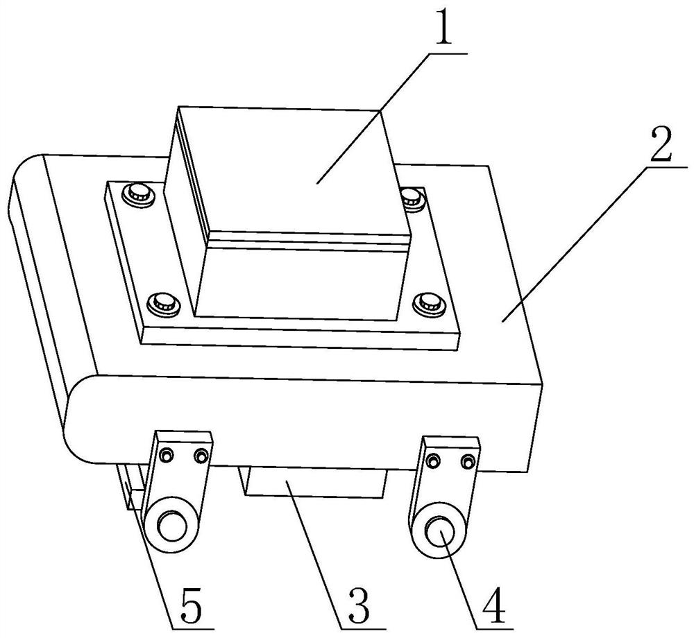
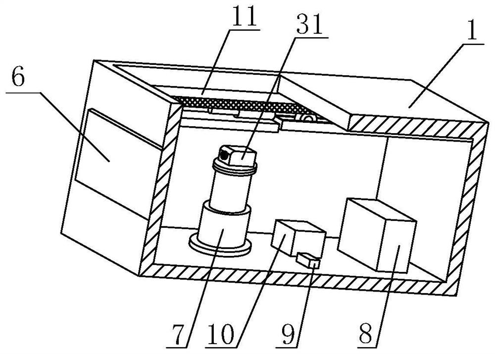
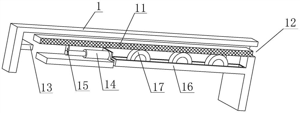
[0034] Such as Figure 1-Figure 8 As shown, the present invention provides an intelligent railway track inspection device, comprising a main body 1 and a bearing base 2, the bottom of the main body 1 is threadedly connected with the bearing base 2, the bottom of the bearing base 2 is provided with a drive wheel 4, and the drive wheel 4 One side is provided with a clearing device 5 and a driving device 3, the outer wall of the main body 1 is inlaid with a perspective window 6, and the inner wall of the main body 1 is provided with a movable plate 11, a first telescopic rod 7, a storage battery 8, a processing module 9 and a light energy conversion In the device 10, the terminal line of the processing module 9 is connected with a storage battery 8, the top of the first telescopic rod 7 is fixedly mounted with a turntable, and the top of the turntable is threaded with a video recorder 31, and the terminal line of the video recorder 31 is connected with a processing Module 9 and b...
Embodiment 2
[0038] Such as Figure 4 , Figure 5 As shown, on the basis of Embodiment 1, the present invention provides a technical solution: the front of the obstacle removal device 5 is provided with a distance sensor 18 and a connecting plate 19, and the connecting plate 19 is located on the left and right sides of the distance sensor 18 and arranged symmetrically , the distance sensor 18 can detect whether there is an obstacle ahead, so that the obstacle clearing device 5 works, the left side of the connecting plate 19 is fixedly equipped with a hollow plate 20, and the left side of the hollow plate 20 is slidably connected with a push plate 21, pushing A connecting piece 25 is arranged above the top of the plate 21, and a pneumatic two-way control valve 24 is fixedly installed on the right side of the connecting piece 25. The inner wall of the pneumatic two-way control valve 24 is slidably connected with a slide bar 23, and the front and rear ends of the slide bar 23 are fixedly conn...
Embodiment 3
[0040] Such as Figure 6-7 As shown, on the basis of Embodiment 1 and Embodiment 2, the present invention provides a technical solution: preferably, the driving device 3 includes a frequency conversion motor 26, a shaft device 27 and a transmission rod 28, and the bottom of the frequency conversion motor 26 and the driving device The inner wall of 3 is threadedly connected, the drive end of variable frequency motor 26 is connected with rotating shaft device 27 in rotation, the inner wall of rotating shaft device 27 is connected with transmission rod 28 in rotation, and transmission rod 28 is positioned at the left and right ends of rotating shaft device 27 and arranged symmetrically, the wiring of variable frequency motor 26 The terminal line is connected with the processing module 9 and the storage battery 8, and one end of the transmission rod 28 is connected to the drive wheel 4 in rotation on the side away from the driving device 3, and the transmission rod 28 on both sides...
PUM
 Abstract
Description
Claims
Application Information
 - R&D
- Intellectual Property
- Life Sciences
- Materials
- Tech Scout
- Unparalleled Data Quality
- Higher Quality Content
- 60% Fewer Hallucinations
Browse by: Latest US Patents, China's latest patents, Technical Efficacy Thesaurus, Application Domain, Technology Topic, Popular Technical Reports.
© 2025 PatSnap. All rights reserved.Legal|Privacy policy|Modern Slavery Act Transparency Statement|Sitemap|About US| Contact US: help@patsnap.com


