Underground pressure release valve and hydraulic shaping pipe column

A pressure relief valve and hydraulic technology, applied in the direction of wellbore/well valve device, wellbore/well parts, earthwork drilling and production, etc., can solve problems such as troublesome operation, safety risk, low repair efficiency, etc., and achieve pressure relief speed Fast, improve the efficiency of pressure relief, improve the effect of shaping efficiency

Active Publication Date: 2021-03-30
CHINA PETROLEUM & CHEM CORP +1
View PDF10 Cites 1 Cited by
  • Summary
  • Abstract
  • Description
  • Claims
  • Application Information

AI Technical Summary

Problems solved by technology

In the actual construction process, the damaged part of the casing often needs multiple and multi-stage plastic surgery. After the pressure pump on the ground is pressurized, manual pressure relief is required to release the hydraulic anchor. Frequent pressure boosting and pressure release operations are not only cumbersome to operate , the repair efficiency is low, and it also brings a greater safety risk to the ground construction operations

Method used


Image

  • Underground pressure release valve and hydraulic shaping pipe column
  • Underground pressure release valve and hydraulic shaping pipe column
  • Underground pressure release valve and hydraulic shaping pipe column

Examples


specific Embodiment 1

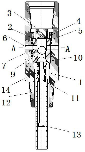
[0066] The downhole pressure relief valve of the present invention is installed in the hydraulic shaping pipe string when in use, and can automatically remove the pressure in the hydraulic shaping pipe string under certain trigger conditions. The installation position in the hydraulic shaping string and the connection relationship with other components in the hydraulic shaping string are introduced: the downhole pressure relief valve of the present invention is installed between the hydraulic anchor and the hydraulic booster when used, such as figure 1 As shown, the downhole pressure relief valve includes an outer sleeve 1, and the upper end of the outer sleeve 1 is provided with an internal thread section for connecting with the hydraulic anchor. The lower end of the outer casing 1 is provided with an external thread section for connecting with the cylinder body of the hydraulic booster, and the external thread section constitutes a lower connection section, and the inside of ...

specific Embodiment 2

[0077] The difference from Embodiment 1 is that the one-way conduction structure is a one-way valve installed at the liquid outlet, and the one-way valve includes two ring protrusions located at intervals inside the liquid outlet and protruding radially inward. In the direction in which the liquid in the valve seat flows out from the liquid outlet hole, the ring protrusion located upstream is the upstream ring protrusion, and the ring protrusion located downstream is the downstream ring protrusion. A spring and a small ball are installed between the two ring protrusions, and one end of the spring touches the top. On the downstream ring convex, the other end pushes the small ball against the middle hole of the upstream ring convex to block it. When the liquid in the outer casing flows out from the liquid outlet hole, it can flow out from the middle hole on the upstream ring protrusion and the downstream ring protrusion by overcoming the elastic force of the spring. The one-way ...

specific Embodiment 3

[0079]Different from Embodiment 1, the inner hole at the lower end of the valve seat is provided with a downward annular groove, and the valve core includes an upper valve column and a lower trigger rod, and the valve column is threadedly connected with the trigger rod. The outer peripheral surface of the spool is provided with a sealing ring for sealing cooperation with the side wall of the ring groove of the valve seat. The ring groove constitutes a valve port for matching with the valve core. between.


PUM


Abstract

The invention discloses an underground pressure release valve and a hydraulic shaping pipe column. The underground pressure release valve comprises an outer sleeve, a valve seat, a valve element and apiston connecting piece, wherein a liquid outlet hole is formed in the outer sleeve, the valve seat is fixed in the outer sleeve and is in sealing fit with the outer sleeve, a pressurizing channel and a pressure release channel are formed in the valve seat, the piston connecting piece can move downwards along with a piston of a hydraulic booster when pressurizing the interior of the outer sleeve,a transmission relation is established between the piston connecting piece and the valve element when the piston connecting piece moves downwards by a certain distance, and the valve element is disengaged from the valve seat to communicate the pressure relief channel. According to the underground pressure release valve, when the piston connecting piece descends to a certain position, the valve element can be automatically driven to be disengaged from the valve seat, the pressure release channel is connected, then the hydraulic shaping column automatically releases pressure, the whole pressurerelease process is conducted underground, frequent pressure rising and releasing on the ground manually are not needed, the pressure release speed is high, the process is safe and reliable, manpowerand material resources can be saved, and pipe column shaping efficiency can be improved.

Description

technical field [0001] The invention relates to an underground pressure relief valve and a hydraulic shaping pipe string. Background technique [0002] After years of development in the oilfield, the well conditions are getting worse day by day, the number of wells with casing damage is increasing, various technological measures in the oilfield cannot be implemented, the production plan is affected, and the injection-production system is out of balance, and a large number of oil-water wells lie down. As an advanced workover technology, hydraulic shaping technology is particularly important in its application. [0003] The hydraulic shaping string is generally equipped with a hydraulic anchor, a hydraulic booster and a shaper from top to bottom, and the hydraulic booster includes a cylinder and a piston. When the hydraulic shaping string is applied, it is necessary to pressurize the shaping string on the ground. After the hydraulic anchor is anchored, the hydraulic shaping s...

Claims


Application Information

Patent Timeline
Patent Type & Authority Applications(China)
IPC IPC(8): E21B34/08E21B34/14E21B29/10
CPCE21B34/08E21B34/14E21B29/10
Inventor 王新志陈景谢晋朱辉马宏伟范钰玮杨佰阳李辉
Owner CHINA PETROLEUM & CHEM CORP
Why Eureka
Try Eureka