Thermally conductive polymer composite material with multi-level continuous network structure and preparation method

A network structure and composite material technology, applied in the field of thermally conductive polymer composite materials and preparation, can solve the problems of a single three-dimensional continuous thermally conductive network structure, heat transfer, large average distance, etc., and achieve simple and easily available raw materials, high thermal conductivity, average small distance effect

Active Publication Date: 2022-07-15
济南英维新材料科技合伙企业(有限合伙)
View PDF4 Cites 0 Cited by
  • Summary
  • Abstract
  • Description
  • Claims
  • Application Information

AI Technical Summary

Problems solved by technology

Existing research has made a series of progress in the construction of three-dimensional continuous heat conduction network and the improvement of thermal conductivity of composite materials. However, the existing three-dimensional continuous heat conduction network has a single structure, and the average distance between the network skeleton and the polymer matrix is ​​large, which is not conducive to heat conduction. The filler exerts its own high thermal conductivity
For example, Lin et al. used graphene network to enhance the thermal conductivity of epoxy resin, in which the mass fraction of graphene reached 5%, and the thermal conductivity of the composite material was 1.52W / mK, which was far lower than the theoretical thermal conductivity of graphene of 5300W / mK. This is because the distance between the graphene thermal network and the polymer matrix is ​​too large, and it is difficult for heat to quickly transfer from the polymer matrix to the thermal network.

Method used


Image

  • Thermally conductive polymer composite material with multi-level continuous network structure and preparation method
  • Thermally conductive polymer composite material with multi-level continuous network structure and preparation method
  • Thermally conductive polymer composite material with multi-level continuous network structure and preparation method

Examples


Embodiment 1

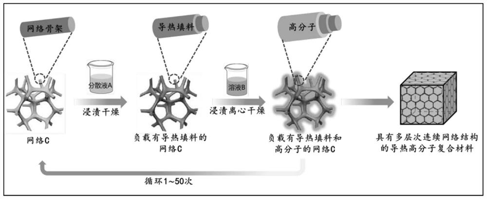
[0036] like figure 1 As shown, a preparation method of a thermally conductive polymer composite material with a multi-level continuous network structure comprises the following steps:

[0037]Prepare a network C, which is a polyurethane network with a pore size of 150 μm. Carry out the loading method for network C 50 times, each loading method is: immersing in dispersion A for 30 min, taking out and drying at 20°C for 0.5 h to obtain network C loaded with thermally conductive fillers, and immersing network C loaded with thermally conductive fillers solution B for 30min, taken out, centrifuged at 2000r / min for 30min, and dried at 20°C for 300min to obtain a thermally conductive polymer composite material, wherein,

[0038] The preparation method of dispersion liquid A is as follows: dispersing the thermally conductive filler in liquid D to obtain a mixture, ultrasonically treating the mixture with a cell crusher for 60 min to obtain dispersion liquid A, the power of ultrasonic...

Embodiment 2

[0056] A preparation method of a thermally conductive polymer composite material with a multi-level continuous network structure, comprising the following steps:

[0057] Prepare a network C, which is a melamine network with a pore size of 100 μm. Carry out the loading method for network C 50 times, each loading method is: immersing in dispersion A for 1 min, taking out and drying at 50 ° C for 1 h to obtain a network C loaded with thermally conductive fillers, and immersing network C loaded with thermally conductive fillers in the solution B for 20min, take out, centrifuge at 1000r / min for 15min, and dry at 50°C for 200min to obtain a thermally conductive polymer composite material, wherein,

[0058] The preparation method of dispersion A is as follows: dispersing the thermally conductive filler in liquid D to obtain a mixture, ultrasonically treating the mixture with a cell crusher for 5 min to obtain dispersion A, the power of ultrasonic treatment is 800W, and the concentra...

Embodiment 3

[0062] A preparation method of a thermally conductive polymer composite material with a multi-level continuous network structure, comprising the following steps:

[0063] Prepare a network C, which is a cellulose network with a pore size of 50 μm. Carry out the loading method for network C 50 times, each loading method is: immersing in dispersion A for 10 min, taking out and drying at 50°C for 3 h to obtain network C loaded with thermally conductive fillers, and immersing network C loaded with thermally conductive fillers into the solution B for 1 min, take out, centrifuge at 500 r / min for 15 min, and dry at 50 °C for 30 min to obtain a thermally conductive polymer composite material, wherein,

[0064] The preparation method of dispersion liquid A is as follows: dispersing the thermally conductive filler in liquid D to obtain a mixture, and ultrasonically treating the mixture with a cell crusher for 30 min to obtain dispersion liquid A, the power of ultrasonic treatment is 500...


PUM

PropertyMeasurementUnit
concentrationaaaaaaaaaa
pore sizeaaaaaaaaaa
pore sizeaaaaaaaaaa

Abstract

The invention discloses a thermally conductive polymer composite material with a multi-level continuous network structure and a preparation method. A network C is prepared, and the network C is loaded for 2 to 50 times. After taking out, it is dried at a temperature of 20 to 200 ° C to obtain a network C loaded with thermally conductive fillers, and the network C loaded with thermal conductive fillers is immersed in solution B. After taking out, it is dried at a temperature of 20 to 320 ° C for 30 to 300 minutes to obtain high thermal conductivity. Molecular composite material, the raw materials required by the preparation method of the present invention are simple and easy to obtain, through a simple impregnation process, the thermally conductive filler can form a multi-level three-dimensional continuous thermally conductive network, and by controlling the number of loads, high thermal conductivity with different thermal conductivity can be obtained. Molecular composites. The average distance between the polymer matrix of the thermally conductive polymer composite and the thermally conductive filler network is small, and the thermal conductivity is high.

Description

technical field [0001] The invention belongs to the technical field of heat-conducting materials, and in particular relates to a heat-conducting polymer composite material with a multi-level continuous network structure and a preparation method. Background technique [0002] With the rapid development of 5G communication, high-integration chips, artificial intelligence, etc., the power density and heat production of electronic devices have greatly increased. If there is no sufficient thermal management guarantee, it is easy to cause premature aging or damage of related devices. Traditional metal thermal conductive materials (such as aluminum, copper, etc.) have been difficult to achieve due to the limitations of high density, low specific thermal conductivity (ratio of thermal conductivity to material bulk density), high thermal expansion coefficient, and easy oxidation. To meet the current growing demand for cooling. Polymer composites reinforced with thermally conductive ...

Claims


Application Information

Patent Timeline
Patent Type & Authority Patents(China)
IPC IPC(8): C08J9/42C08L75/04C08L29/04C08K3/04C08L61/28C08L71/02C08L1/02C08K7/00C08K3/08C08L79/08C08L23/12C08K3/38C08L33/02C08L79/02C08K7/24C08K3/28C08L83/04C08L63/00C08J3/21C09K5/14
CPCC08J9/42C08J3/215C08J3/212C09K5/14C08J2375/04C08K3/041C08J2429/04C08J2361/28C08J2471/02C08J2301/02C08J2401/02C08K7/00C08K2003/0806C08J2379/08C08J2479/08C08K3/042C08J2323/12C08J2433/02C08K2003/385C08K7/24C08K2003/0862C08J2379/02C08K3/04C08K3/28C08K3/046C08J2483/04C08K2003/085C08J2363/00
Inventor 秦盟盟陈莉
Owner 济南英维新材料科技合伙企业(有限合伙)
Why Eureka
Try Eureka