
Outer conductor electrode structure of homogenized planar photoconductive switch electric field, photoconductive switch device and method

A technology of photoconductive switch and electrode structure, applied in semiconductor devices, electrical components, circuits, etc., can solve the problems of surface flashover, reduce the voltage withstand capability of the device, limit the life of the device, etc., achieve the homogenization of the electric field distribution, and improve the withstand voltage capability. , Improve the effect of flatness

Active Publication Date: 2021-03-26
XI AN JIAOTONG UNIV
View PDF14 Cites 0 Cited by
  • Summary
  • Abstract
  • Description
  • Claims
  • Application Information

AI Technical Summary

Problems solved by technology

Under higher operating voltage and operating current, power semiconductor devices often need to withstand high electric fields, which are prone to flashover or breakdown along the surface, which seriously affects the normal operation of the device, and even completely fails the device
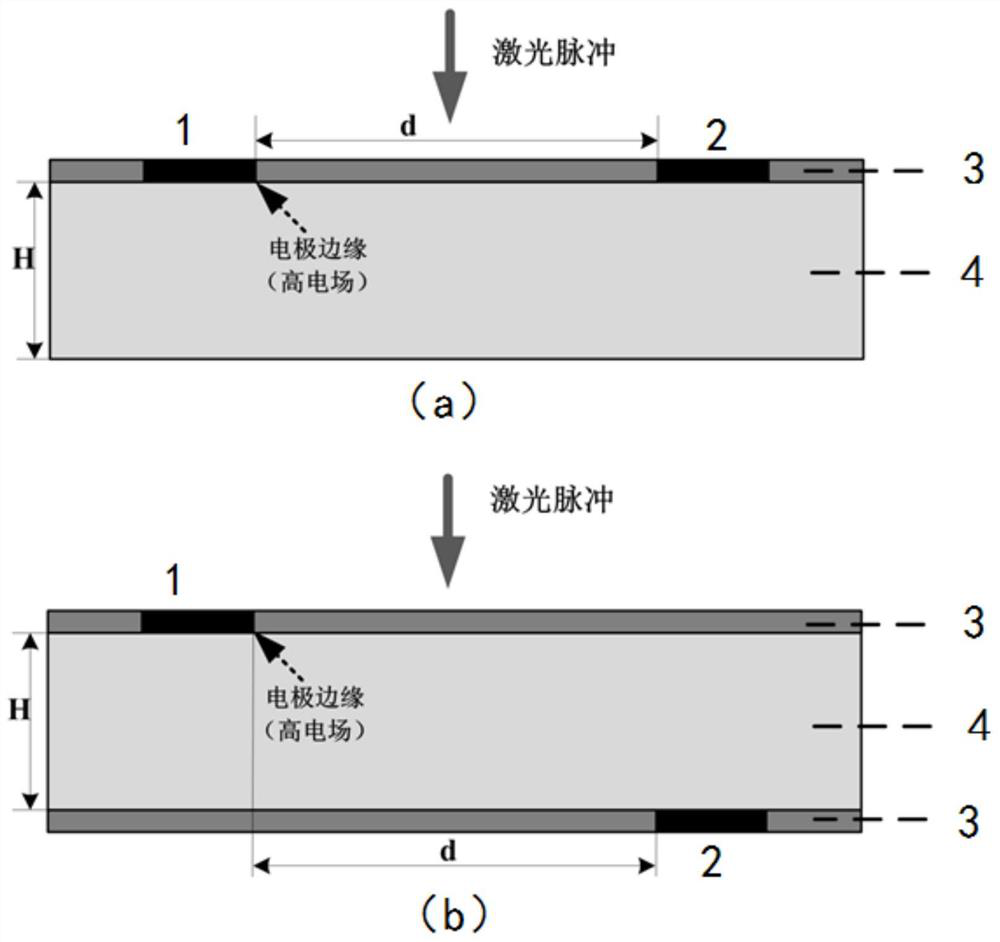
For planar photoconductive switches, the electric field inside the device exhibits non-uniform distribution characteristics under high bias voltage, especially at the edge of the electrode, which has a very high electric field distribution, which is more than 2 orders of magnitude higher than the theoretical average electric field inside the device. , which makes the device very easy to accumulate damage on the edge of the electrode during the working process, which seriously limits the life of the device under pulse bias voltage, and corona discharge is prone to occur under DC bias voltage, which seriously reduces the withstand voltage capability of the device

Method used


Image

  • Outer conductor electrode structure of homogenized planar photoconductive switch electric field, photoconductive switch device and method
  • Outer conductor electrode structure of homogenized planar photoconductive switch electric field, photoconductive switch device and method
  • Outer conductor electrode structure of homogenized planar photoconductive switch electric field, photoconductive switch device and method

Examples


Embodiment Construction

[0024] In order to enable those skilled in the art to better understand the solutions of the present invention, the following will clearly and completely describe the technical solutions in the embodiments of the present invention in conjunction with the drawings in the embodiments of the present invention. Obviously, the described embodiments are only It is an embodiment of a part of the present invention, but not all embodiments. Based on the embodiments of the present invention, all other embodiments obtained by persons of ordinary skill in the art without making creative efforts shall fall within the protection scope of the present invention.

[0025] It should be noted that the terms "first" and "second" in the description and claims of the present invention and the above drawings are used to distinguish similar objects, but not necessarily used to describe a specific sequence or sequence. It is to be understood that the data so used are interchangeable under appropriate ...


PUM


Abstract

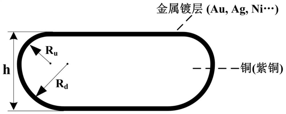
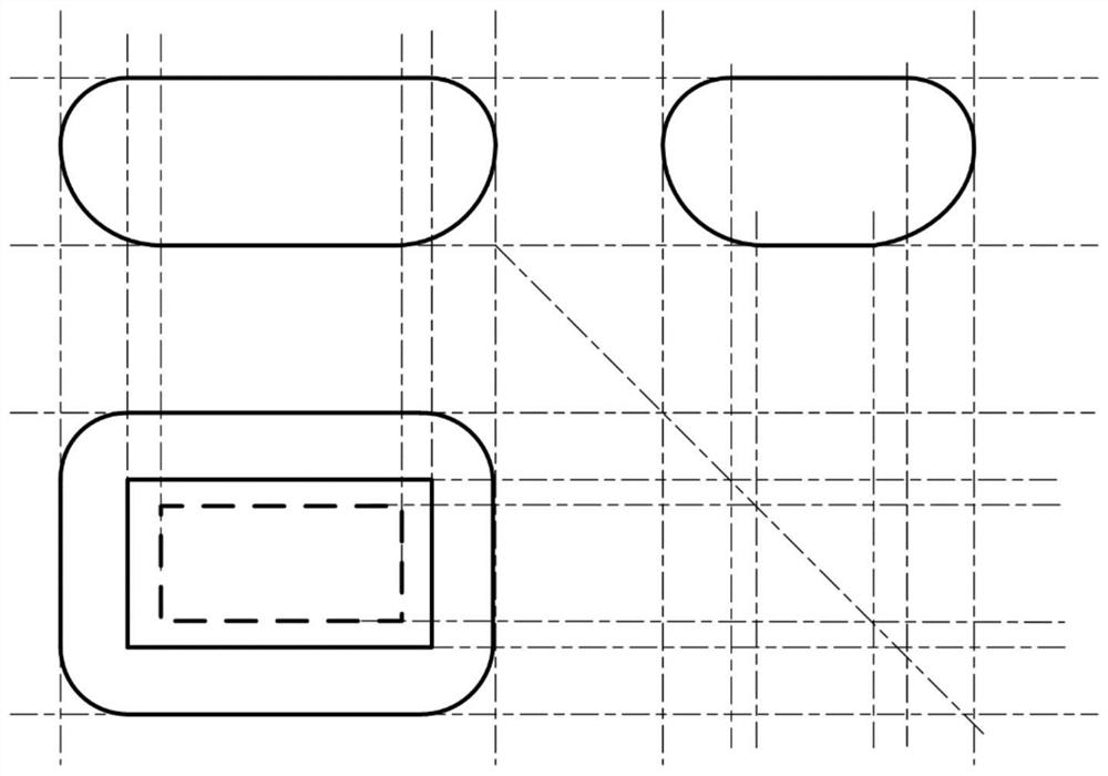
The invention discloses an outer conductor electrode structure of a homogenized planar photoconductive switch electric field, a photoconductive switch device and a method, and belongs to the technicalfield of pulse power. The outer conductor electrode structure is composed of a metal cube block material, and the surface of the metal cube block material is plated with at least one metal plating layer. Moreover, the upper side edge and the lower side edge of the outer conductor electrode structure form a chamfer structure, electric field intensity of the electrode edge of the device is effectively reduced, a voltage endurance capability of the device is remarkably improved and a damage to the electrode edge is inhibited, reliability of the device during operation is improved, and the service life of the device is prolonged. And meanwhile, an outer conductor can quickly transfer heat generated at the edge of the electrode when the device continuously works by virtue of good thermal conductivity of the outer conductor so that thermal damage is avoided.

Description

technical field [0001] The invention belongs to the technical field of pulse power, and in particular relates to an outer conductor electrode structure for homogenizing the electric field of a planar photoconductive switch, a photoconductive switch device and a method. Background technique [0002] With the development of pulse power technology, high-power semiconductor devices represented by solid-state switches are gradually replacing traditional devices such as gas switches, vacuum switches, and plasma switches due to their characteristics and advantages of high energy efficiency, high repetition frequency, and miniaturization. . However, as power increases, higher requirements are placed on the reliability and lifetime of high-power semiconductor devices. Under higher operating voltage and operating current, power semiconductor devices often need to withstand high electric fields, which are prone to flashover or breakdown along the surface, which seriously affects the n...

Claims


Application Information

Patent Timeline
IPC IPC(8): H01L31/0224H01L31/024
CPCH01L31/0224H01L31/024Y02P70/50
Inventor 胡龙孙岳朱莉李昕杨向红党鑫李永东
Owner XI AN JIAOTONG UNIV
Learn More