
Laboratory liquid medicine outlet device and control method thereof

A water outlet device and laboratory technology, applied in the direction of measuring devices, lubrication indicating devices, volume measuring instruments/methods, etc., can solve the problems of inability to detect residual liquid volume, difficulty in ensuring the accuracy of liquid medicine, and high price of liquid level sensors. To achieve the effect of avoiding the waste of liquid medicine, avoiding excessive liquid medicine, and improving the efficiency of liquid extraction

Inactive Publication Date: 2021-03-26
CHANGZHOU INST OF LIGHT IND TECH
View PDF0 Cites 0 Cited by
  • Summary
  • Abstract
  • Description
  • Claims
  • Application Information

AI Technical Summary

Problems solved by technology

[0002] Existing non-contact liquid level sensors include ultrasonic liquid level transmitters, radar liquid level transmitters, etc., but the price of liquid level sensors is relatively high, and infrared sensors are often used in laboratories to detect the liquid level of liquid medicine. In order to control the amount of liquid medicine, due to the different concentration and adhesion of various liquid medicines, it often happens that there is residual liquid in the pipeline and on the inner wall of the reactor when detecting the water outlet device, which cannot be detected by the infrared sensor. The volume of the residual liquid, and then the residual liquid slowly enters the reactor, which affects the dosage of the liquid medicine, and it is difficult to ensure the accuracy of the liquid medicine measurement

Method used


Image

  • Laboratory liquid medicine outlet device and control method thereof
  • Laboratory liquid medicine outlet device and control method thereof
  • Laboratory liquid medicine outlet device and control method thereof

Examples


Embodiment Construction

[0056] The present invention will be further described below in conjunction with the accompanying drawings. The following examples are only used to illustrate the technical solution of the present invention more clearly, but not to limit the protection scope of the present invention.

[0057] In the description of the present invention, it should be noted that the terms belonging to "center", "upper", "lower", "left", "right", "vertical", "horizontal", "inner", "outer" etc. The indicated orientation or positional relationship is based on the orientation or positional relationship shown in the drawings, and is only for the convenience of describing the present invention and simplifying the description, rather than indicating or implying that the referred device or element must have a specific orientation, or in a specific orientation. construction and operation, therefore, should not be construed as limiting the invention.

[0058] In the description of the present invention, ...


PUM


Abstract

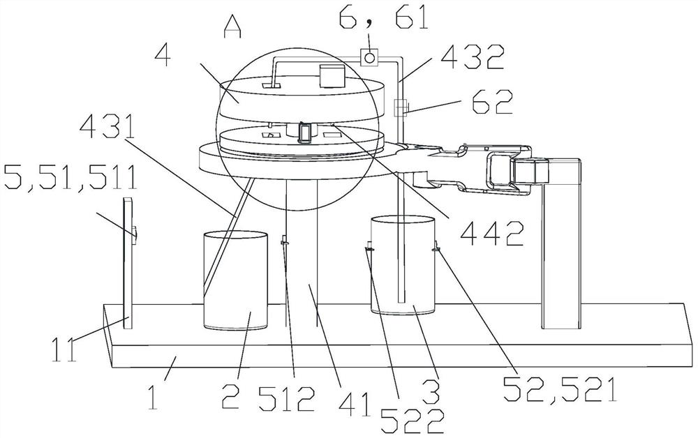
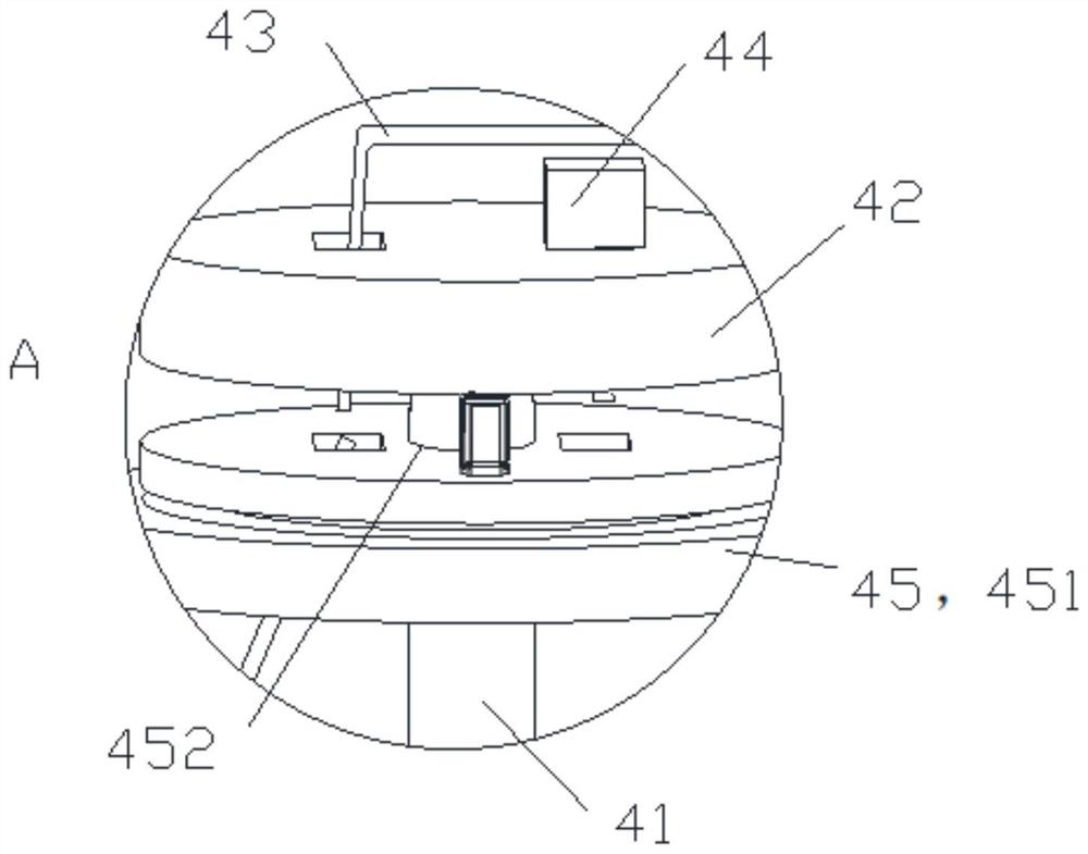
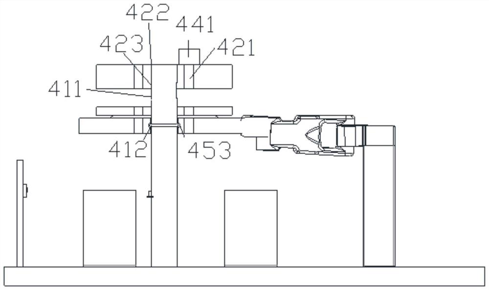
The invention relates to a laboratory liquid medicine outlet device which comprises a mounting base, and a reaction kettle, a liquid storage tank, a liquid guide device, a detection device and a liquid suction mechanism which are arranged on the mounting base; the detection device is used for detecting the liquid outlet amount of liquid medicine, and the liquid guide device comprises a stand column, a mounting plate, a liquid guide mechanism, a cleaning mechanism, a rotating mechanism and a driving mechanism; the liquid guide mechanism comprises a liquid inlet pipe of the reaction kettle and aliquid outlet pipe of the liquid storage tank, the cleaning mechanism is used for pressing medicine liquid in the liquid inlet pipe into the reaction kettle, the driving mechanism drives the rotatingmechanism to rotate in the circumferential direction of the stand column, the stand column is sleeved with the rotating mechanism and the mounting plate, and the mounting plate is arranged above therotating mechanism. The mounting plate can move in the vertical direction in the length direction of the stand column. The first infrared detection mechanism and the second infrared detection mechanism are arranged to monitor the liquid outlet amount and the liquid inlet amount in real time, the accuracy of the detection device for detecting the dosage of liquid medicine is improved, and the liquid taking efficiency is improved.

Description

technical field [0001] The invention relates to a water outlet device, in particular to a laboratory medicinal liquid water outlet device. Background technique [0002] Existing non-contact liquid level sensors include ultrasonic liquid level transmitters, radar liquid level transmitters, etc., but the price of liquid level sensors is relatively high, and infrared sensors are often used in laboratories to detect the liquid level of liquid medicine. In order to control the amount of liquid medicine, due to the different concentration and adhesion of various liquid medicines, it often happens that there is residual liquid in the pipeline and on the inner wall of the reactor when detecting the water outlet device, which cannot be detected by the infrared sensor. The volume of the residual liquid, and then the residual liquid slowly enters the reactor, which affects the dosage of the liquid medicine, and it is difficult to ensure the accuracy of the liquid medicine measurement. ...

Claims


Application Information

Patent Timeline
Patent Type & Authority Applications(China)
IPC IPC(8): G01F23/292G01F22/00
CPCG01F22/00G01F23/292
Inventor 王乾
Owner CHANGZHOU INST OF LIGHT IND TECH
Learn More