A drying device for alumina production and processing

A drying device, alumina technology, applied in the direction of drying gas arrangement, drying solid materials without heating, drying solid materials, etc., can solve the problems of rapid dehydration of alumina powder, and achieve the effect of increasing drying and dehydration effect.

Active Publication Date: 2022-04-08
湖南嘉顺华新材料有限公司
View PDF0 Cites 0 Cited by
  • Summary
  • Abstract
  • Description
  • Claims
  • Application Information

AI Technical Summary

Problems solved by technology

[0005] The object of the present invention is to propose a drying device for alumina production and processing in order to solve the problem of rapid dehydration of alumina powder

Method used


Image

  • A drying device for alumina production and processing
  • A drying device for alumina production and processing
  • A drying device for alumina production and processing

Examples


Embodiment 1

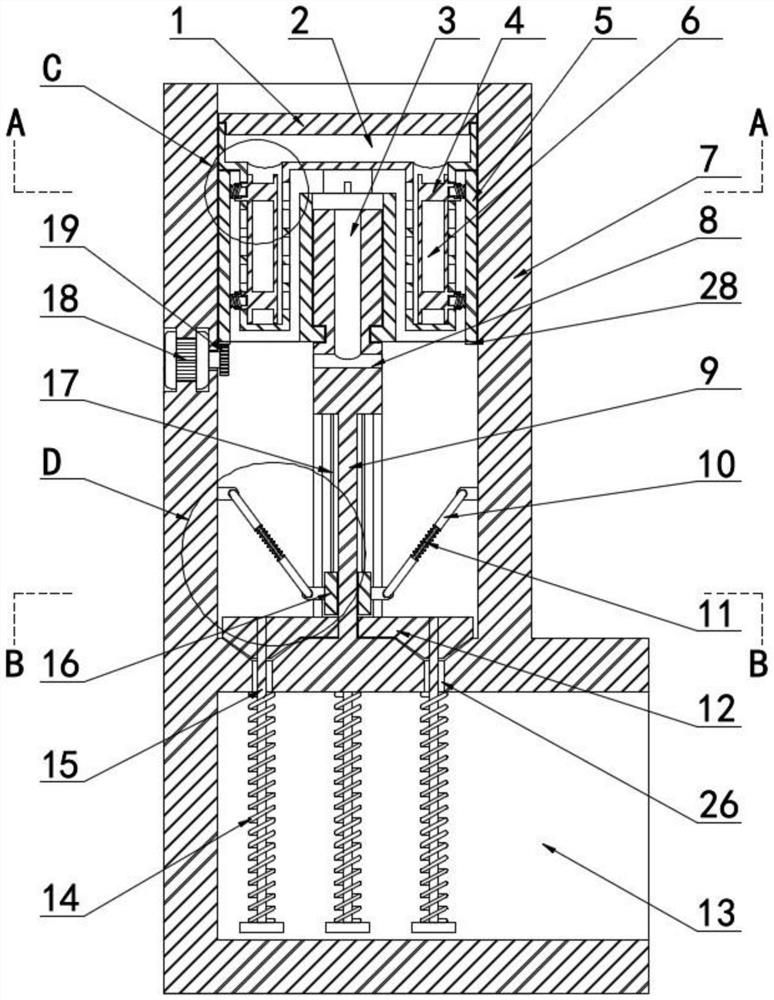
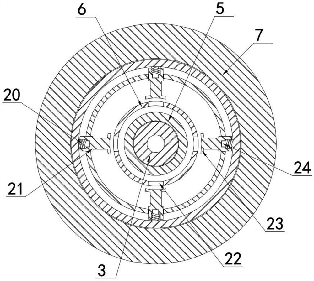
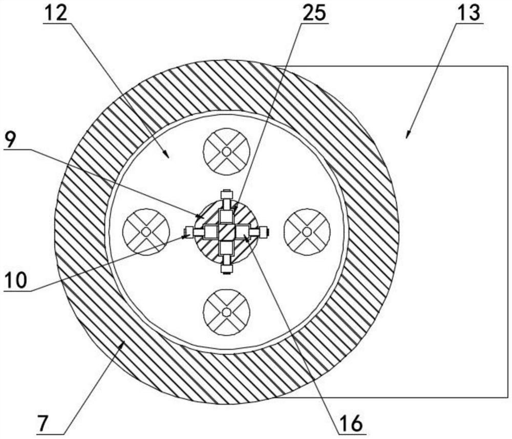
[0034] Embodiment one, with reference to Figure 1-5 , a drying device for alumina production and processing, including a vertical cylindrical shell 7 and a horizontal cylindrical shell 13 fixedly connected to the bottom of the vertical cylindrical shell 7, the center of the vertical cylindrical shell 7 A central fixed installation column 9 is provided, and the outer side of the central fixed installation column 9 is provided with a centrifugal separation and dehydration rotary sleeve 5, and the centrifugal separation and dehydration rotary sleeve 5 is abutted with the upper opening receiving cavity plate 2, and the top opening of the upper opening receiving cavity plate 2 The opening is screwed and connected with a protective and airtight upper screw cover 1, and the bottom end of the upper opening accommodation chamber groove plate 2 is fixedly connected with a two-way opening vertical drum 6, and the side of the two-way opening vertical drum 6 is close to the central fixed ins...

Embodiment 2

[0035] Embodiment two, refer to Figure 1-5 , the connection between the vertical cylindrical shell 7 and the horizontal cylindrical shell 13 is fixedly connected with the bottom end of the central fixed installation column 9, and the outer side of the central fixed installation column 9 is provided with a sleeve plate 12, and the bottom end of the sleeve plate 12 is connected to the horizontal The top of the side wall of the cylindrical shell 13 abuts, the bottom end of the centrifugal separation and dehydration rotating sleeve 5 is fixedly connected with an annular meshing rack 28, and the output end of the drive pair 18 is fixedly connected with an meshing gear plate 19, and the meshing gear plate 19 and the annular meshing rack 28 meshing connection, the horizontal inner communication groove 8 communicates with the vertical inner communication groove 3, the top of the vertical inner communication groove 3 communicates with the inner cavity of the centrifugal separation and ...


PUM


Abstract

The invention discloses a drying device for alumina production and processing, which comprises a vertical cylindrical shell and a horizontal cylindrical shell whose bottom end is fixed and connected, and the center of the vertical cylindrical shell is arranged There is a central fixed installation column, and the outer sleeve of the central fixed installation column is provided with a centrifugal separation and dehydration rotating sleeve. The centrifugal separation and dehydration rotating sleeve is abutted with an upper opening accommodating cavity plate, and the top opening of the upper opening accommodating cavity plate is screwed and connected with a protective cover. The upper screw cap is sealed, and the bottom end of the upper opening accommodation cavity is fixedly connected with a vertical rotating cylinder with two-way openings. In the present invention, the telescopic rod-type opening and closing heating mechanism is adopted to realize the drying and air-drying of the straight inner communication groove and the horizontal inner communication groove, and the centrifugal dehydration drying mechanism is adopted to realize the centrifugal effect during the rotation process to be thrown out to increase oxidation The drying and dehydration effect of aluminum adopts the centrifugal locking airway structure, which is convenient for the external airflow to be charged and used dryly, and at the same time, it is convenient to shake out the moisture for dry use.

Description

technical field [0001] The invention relates to the technical field of alumina drying equipment, in particular to a drying device for alumina production and processing. Background technique [0002] Alumina is an inorganic substance with the chemical formula Al 2 o 3 , is a high-hardness compound with a melting point of 2054°C and a boiling point of 2980°C. It is an ionic crystal that can be ionized at high temperatures and is often used in the manufacture of refractory materials; industrial alumina is made of bauxite (Al 2 o 3 ·3H 2 O) and diaspore. For alumina with high purity requirements, it is generally prepared by chemical methods. There are many isomorphous crystals of alumina. There are more than 10 known types, and there are mainly three crystal forms, namely α- Al 2 o 3 , β-Al 2 o 3 , γ-Al 2 o 3 , in which the structure is different and the properties are different, and it is almost completely transformed into α-Al at a high temperature above 1300 °C 2 o...

Claims


Application Information

Patent Timeline
Patent Type & Authority Patents(China)
IPC IPC(8): F26B11/08F26B5/08F26B21/00F26B25/00F26B25/02
CPCF26B11/08F26B5/08F26B21/004F26B25/00F26B25/02
Inventor 张德强陈伟雄刘明红
Owner 湖南嘉顺华新材料有限公司
Why Eureka
Try Eureka