
Rotor balance process shaft and assembling method thereof

A technology of rotor balancing and process shaft, which is applied in the direction of assembly machines, manufacturing tools, metal processing equipment, etc., can solve the problems of unbalanced machine connection, short axial extension distance of rear journal, etc., to meet design requirements and balance results accurate effect

Pending Publication Date: 2021-03-26
AECC AVIATION POWER CO LTD
View PDF4 Cites 1 Cited by
  • Summary
  • Abstract
  • Description
  • Claims
  • Application Information

AI Technical Summary

Problems solved by technology

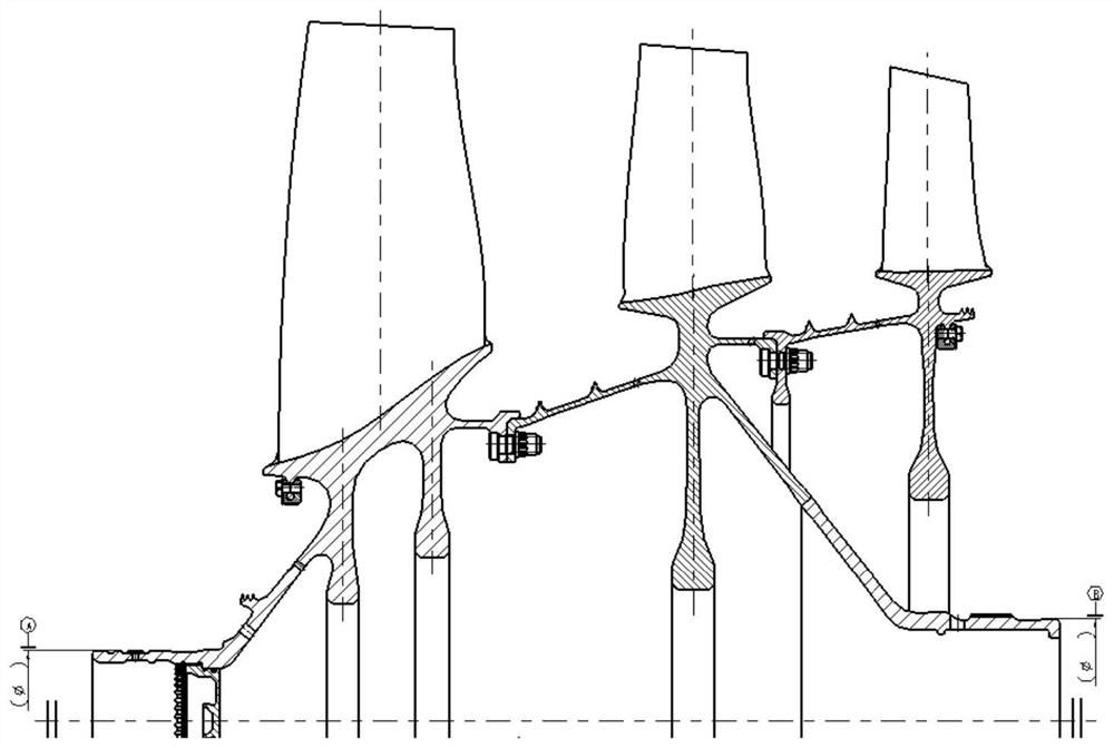
The structure diagram of the compressor rotor of a new scientific research machine is as follows figure 1 As shown, the rear journal of the rotor is designed on the hub of the second-stage blisk. When the third-stage blisk is installed, the axial extension of the rear journal is very short. There is no support shaft, and it cannot be directly balanced machine connection

Method used


Image

  • Rotor balance process shaft and assembling method thereof
  • Rotor balance process shaft and assembling method thereof
  • Rotor balance process shaft and assembling method thereof

Examples


Embodiment Construction

[0031] The present invention is described in further detail below in conjunction with accompanying drawing:

[0032] In the description of the present invention, it should be noted that the terms "center", "upper", "lower", "left", "right", "front", "rear", "vertical", "horizontal", The orientation or positional relationship indicated by "inner", "outer", etc. is based on the orientation or positional relationship shown in the drawings, and is only for the convenience of describing the present invention and simplifying the description, rather than indicating or implying that the referred device or element must have specific orientation, construction and operation in a specific orientation, and therefore should not be construed as limiting the invention; the terms "first", "second" and "third" are used for descriptive purposes only and should not be construed as indicating or implying relative Importance; In addition, unless otherwise clearly stipulated and limited, the terms "...


PUM


Abstract

The invention discloses a rotor balance process shaft and an assembling method thereof. The rotor balance process shaft comprises a welding assembly and a functional shaft, wherein the functional shaft is provided with a first through hole along the axis of the functional shaft; the rear end of the welding assembly penetrates through the first through hole and is inserted into a connecting shaft;and the front end of the welding assembly is inserted into a rear journal end hole of the rotor. The rotor balance process shaft is accurately connected with a balance machine by establishing a rear journal supporting point of the rotor, a balance process for the compressor rotor is completed, an accurate balance result is ensured, and the design requirement is met. By using the balance process shaft, the balance problem that a rotor part which is provided with a short journal and cannot be directly connected with the balance machine due to no supporting point is solved, smooth delivery for the scientific research rotor part is guaranteed, and the structure can be popularized and applied to the balance process for the rotor parts.

Description

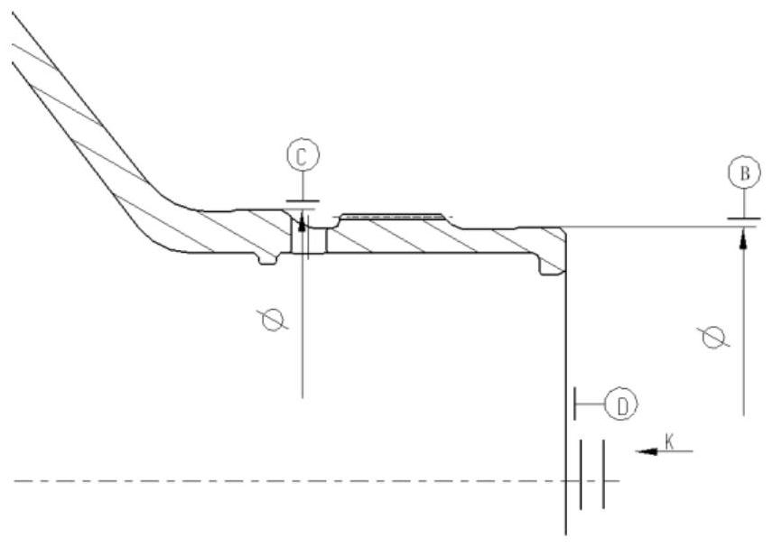
【Technical field】 [0001] The invention belongs to the technical field of aero-engine assembly and inspection, and relates to a rotor balance process shaft and an assembly method thereof. 【Background technique】 [0002] The balance of rotor components has always been a key link in engine assembly, and the accuracy of rotor balance results directly affects the engine test performance. The structure diagram of the compressor rotor of a new scientific research machine is as follows figure 1 As shown, the rear journal of the rotor is designed on the hub of the second-stage blisk. When the third-stage blisk is installed, the axial extension of the rear journal is very short. There is no support shaft, and it cannot be directly balanced machine connection. How to achieve the balance of the rotor components has become a difficult problem to be solved urgently for the scientific research machine. The schematic diagram of the rear journal structure is as follows: figure 2 and i...

Claims


Application Information

Patent Timeline
Patent Type & Authority Applications(China)
IPC IPC(8): F16F15/26F01D5/02B23P21/00
CPCF16F15/264F01D5/02B23P21/00F16F2230/0011
Inventor 王满贤李永民刘小娟赵钊杨翠玲吉建新姚世珍张伟
Owner AECC AVIATION POWER CO LTD
Learn More