
Noise reduction partition plate connecting structure of engine

A connection structure and engine technology, which is applied to the sealing device of the engine, engine components, machine/engine, etc., can solve the problem of unstable connection of the connection structure of the noise reduction partition, achieve stable connection, improve sealing performance, and enhance connection strength Effect

Pending Publication Date: 2021-03-26
ZHEJIANG QIANJIANG MOTORCYCLE
View PDF1 Cites 0 Cited by
  • Summary
  • Abstract
  • Description
  • Claims
  • Application Information

AI Technical Summary

Problems solved by technology

[0006] The purpose of the present invention is to solve the above-mentioned problems in the existing technology, and to propose a connection structure for noise-reducing baffles of an engine. stability problem

Method used


Image

  • Noise reduction partition plate connecting structure of engine
  • Noise reduction partition plate connecting structure of engine
  • Noise reduction partition plate connecting structure of engine

Examples


Embodiment 1

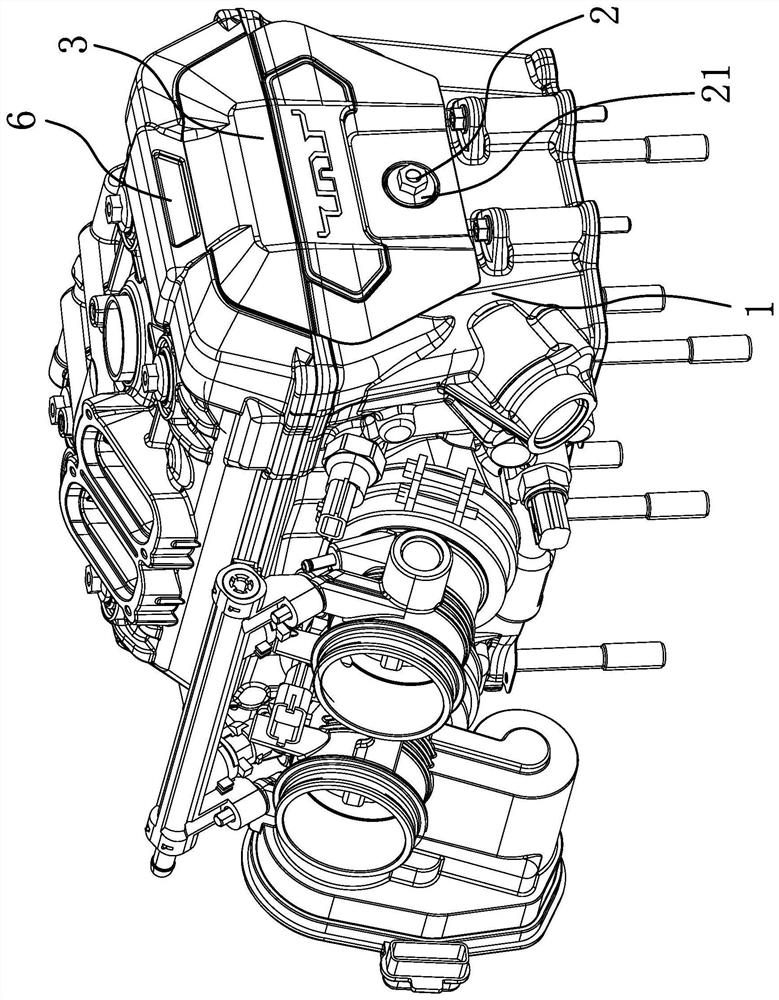
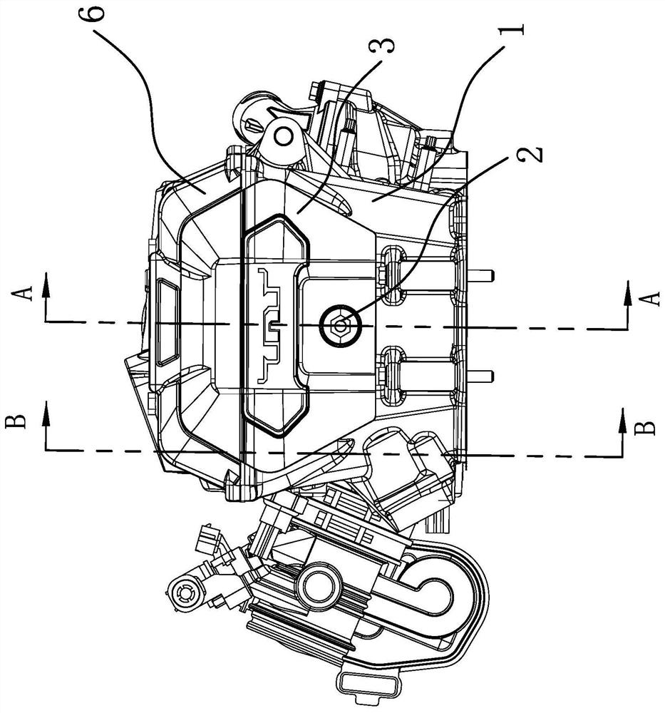
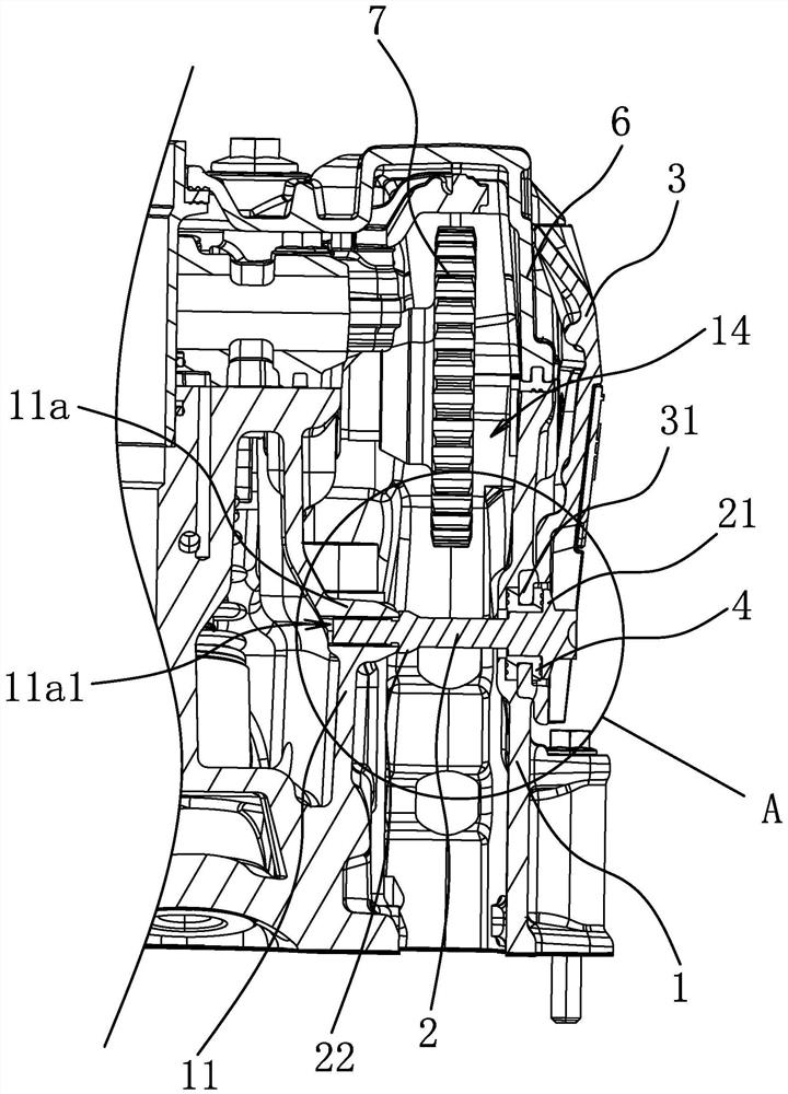
[0040] Such as figure 1 As shown, the connection structure of the noise reduction partition of the engine, the engine includes a cylinder head 1 and a noise reduction partition 3 arranged outside the cylinder head 1, the cylinder head 1 has a fixed part 11, and the connection between the fixed part 11 and the inner wall of the cylinder head 1 A chain chamber 14 is formed between them, a cylinder head 6 is arranged on the cylinder head 1 , and the upper end of the noise reduction partition 3 is located outside the cylinder head 6 .

[0041] Specifically, if Figure 1-6 As shown, the connection structure of the noise reduction partition includes a fixing part 2, and an installation hole is opened on the outer wall of the cylinder head 1. One end of the fixing part 2 passes through the noise reduction partition 3, the installation hole and the chain cavity 14 in sequence and connects with the fixing part 11 Fixed connection, the other end of the fixing part 2 has a fixed retaini...

Embodiment 2

[0049] The content of this embodiment is basically the same as that of Embodiment 1. The difference is that the fixing part 2 is a rivet, and one end of the rivet can pass through the noise reduction partition 3 and the chain cavity 14 in sequence and be fixedly connected with the fixing part 11. The other end of the rivet One end presses the noise reduction partition 3 and the seal 4 against the outer wall of the cylinder head 1 .


PUM


Abstract

The invention provides a noise reduction partition plate connecting structure of an engine, and belongs to the technical field of engines. The noise reduction partition plate connecting structure solves the problem that an existing noise reduction partition plate connecting structure is unstable in connection. According to the noise reduction partition plate connecting structure of the engine, theengine comprises a cylinder head and a noise reduction partition plate arranged outside the cylinder head; a fixing part is arranged in the cylinder head, and a chain cavity is formed between the fixing part and the inner wall of the cylinder head; the noise reduction partition plate connecting structure comprises a fixing part, and a mounting hole is formed in the outer wall of the cylinder head; one end of the fixing part sequentially penetrates through the noise reduction partition plate, the mounting hole and the chain cavity to be fixedly connected with the fixing part, and the other endof the fixing part is provided with a fixing blocking edge for pressing the noise reduction partition plate on the outer wall of the cylinder head; and a sealing part capable of sealing the mountinghole is arranged between the fixing blocking edge and the cylinder head. According to the noise reduction partition plate connecting structure of the engine, connection between the noise reduction partition plate and the cylinder head is more stable, and the stability of the noise reduction partition plate connecting structure is further improved.

Description

technical field [0001] The invention belongs to the technical field of engines, and relates to a connection structure for a noise reduction partition of an engine. Background technique [0002] With the continuous development of science and technology, people use more and more travel tools such as cars and motorcycles. The most important component in a car or motorcycle is the engine. There will be NVH problems when a car or motorcycle is running. The engine is The main source of noise, so it is necessary to optimize the noise reduction of each system of the engine. Since the noise generated by gear transmission accounts for the main part of the whole engine noise, adding a noise reduction device at the front end of the gear chamber can effectively reduce the noise generated by gear transmission from spreading outward, thereby effectively reducing the overall noise of the engine. [0003] In response to the above problems, people have developed a variety of noise reduction ...

Claims


Application Information

Patent Timeline
Patent Type & Authority Applications(China)
IPC IPC(8): F02B77/13F02F1/24F02F11/00
CPCF02B77/13F02F1/24F02F11/002
Inventor 张立成邓定红程雪君李良周鹏博
Owner ZHEJIANG QIANJIANG MOTORCYCLE
Learn More