A fast cleaning electrochemical water treatment equipment
A kind of water treatment equipment, electrochemical technology, applied in the field of water treatment, can solve the problems of more cleaning liquid consumption, cleaning effect and low efficiency, and achieve the effect of increasing processing efficiency, saving cleaning liquid and increasing processing capacity
- Summary
- Abstract
- Description
- Claims
- Application Information
AI Technical Summary
Problems solved by technology
Method used
Image
Examples
Embodiment 1
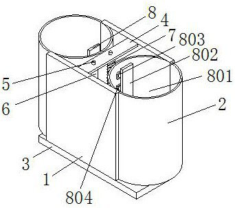
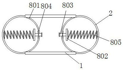
[0040] Example 1: Please refer to Figure 1-2 , the present invention proposes a fast cleaning electrochemical water treatment equipment, including front and rear side plates 1, left and right side plates 2, bottom plate 3, top plate 4 and adjustment mechanism 8, the number of front and rear side plates 1 is two and the front and rear are corresponding , the number of the left and right side plates 2 is two and they are fixedly connected to the two sides of the two front and rear side plates 1 respectively. The shape of the left and right side plates 2 is a semi-circular body with corresponding curved surfaces. It is arranged on the top surface of the bottom plate 3, the top plate 4 is fixedly connected to the top of the corresponding surfaces of the two front and rear side plates 1, the top surface of the top plate 4 is fixedly installed with two connecting posts 5, and the bottom surface of the top plate 4 is fixedly installed with a conductive column 6 and an electromagnet. ...
Embodiment 2
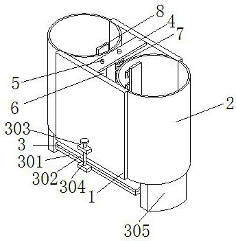
[0041] Example 2: Please refer to image 3 , on the basis of the first embodiment, the bottom plate 3 includes a connecting plate 301 and a fixing plate 303, the connecting plate 301 is arranged on the bottom surface of the front and rear side plates 1 and the left and right side plates 2, and the front surface of the connecting plate 301 and the front surface of the front and rear side plates 1 are A fixing plate 303 is fixedly connected, the upper fixing plate 303 is provided with a hole in the center and a screw 304 is inserted into it, the lower fixing plate 303 is provided with a threaded hole in the center and is threadedly connected with the screw 304, the top surface of the connecting plate 301 is fixedly connected with a rubber pad 302, The bottom surfaces of the two left and right side plates 2 are fixedly connected with a support plate 305. By rotating the fixed plate 303, the bottom plate 3 and the bottom surface of the front and rear side plates 1 can be separated ...
Embodiment 3
[0042] Example 3: Please refer to Figure 4-6 , On the basis of the first embodiment, the left and right side plates 2 are provided with a water supply mechanism 9. The water supply mechanism 9 includes a cushion 901 and a water pipe 902. The center of the sleeve 803 and the interior of the magnetic plate 802 are in a hollow state. The side of 802 away from the rubber side plate 801 is provided with a hole, the water pipe 902 is a hollow cylinder, the number of the water pipe 902 is multiple and is fixedly connected to the side corresponding to the sleeve 803 on the two adjustment mechanisms 8 respectively, and the cover pad 901 sets It is inserted into the outer wall of the water pipe 902 and the side is fixedly connected with the rubber side plate 801. The center of the side of the cover pad 901 away from the rubber side plate 801 is in a separated state. At a position away from the center of the cover pad 901, when water is injected into the front and rear side plates 1 and...
PUM
 Abstract
Description
Claims
Application Information
 - R&D
- Intellectual Property
- Life Sciences
- Materials
- Tech Scout
- Unparalleled Data Quality
- Higher Quality Content
- 60% Fewer Hallucinations
Browse by: Latest US Patents, China's latest patents, Technical Efficacy Thesaurus, Application Domain, Technology Topic, Popular Technical Reports.
© 2025 PatSnap. All rights reserved.Legal|Privacy policy|Modern Slavery Act Transparency Statement|Sitemap|About US| Contact US: help@patsnap.com


