
Rotating joint and robot

A technology of rotating joints and joints, which is used in manipulators, transportation and packaging, stacking of objects, etc., can solve the problems of increased stress at the rotating joints of robots, uneven force on the rotating joints of robots, and unreasonable structural design of robots. Achieve the effect of shortening maintenance time, avoiding premature wear and improving design depth

Active Publication Date: 2021-03-26
伯朗特机器人股份有限公司
View PDF11 Cites 3 Cited by
  • Summary
  • Abstract
  • Description
  • Claims
  • Application Information

AI Technical Summary

Problems solved by technology

[0003] The robot's rotating joint is an important part of the robot. The existing robot joints will cause the stress at the robot's rotating joint to increase suddenly when the bearing fails, gets stuck, or is subjected to an impact load, resulting in damage or even fracture.
In addition, the overall structural design of the robot is unreasonable, which also causes uneven force on the rotating joints of the robot, which shortens the life of the bearings and damages the rotating joints of the robot.

Method used


Image

  • Rotating joint and robot
  • Rotating joint and robot
  • Rotating joint and robot

Examples


Embodiment Construction

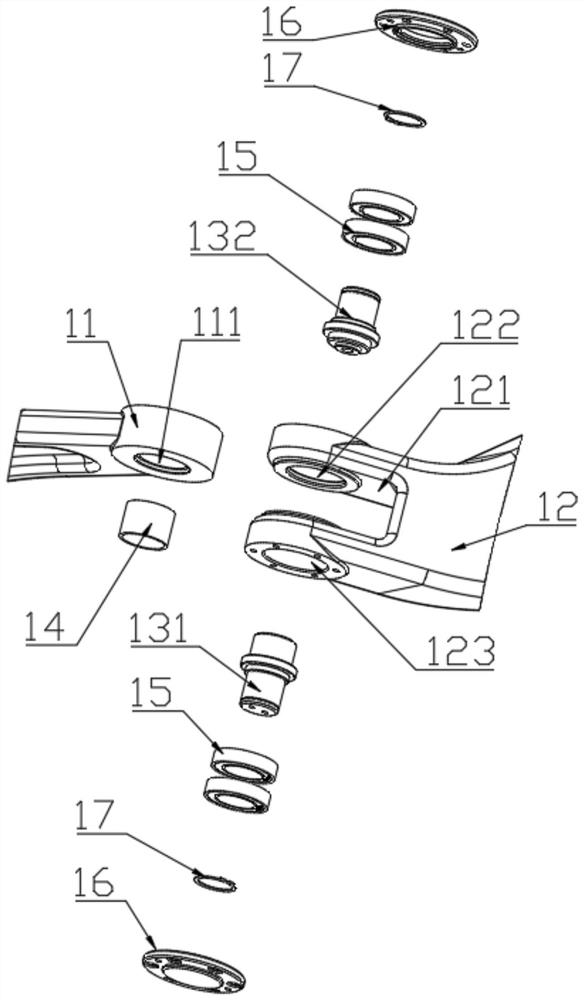
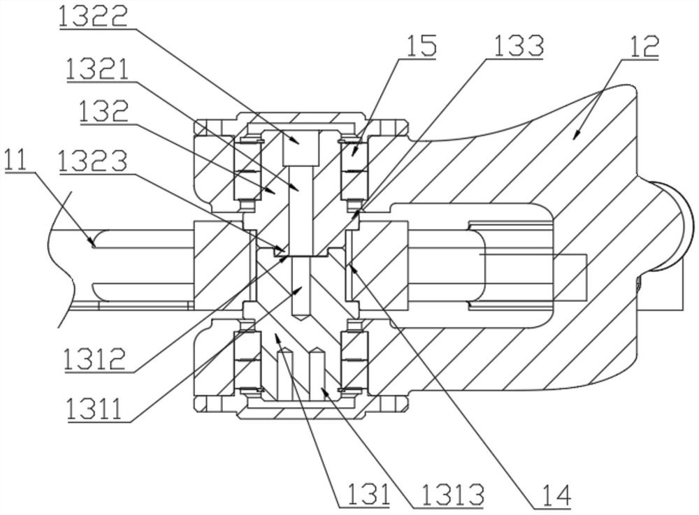
[0056] see Figure 1 to Figure 6 , a rotary joint in this embodiment, including a first joint body 11, a second joint body 12, a rotating shaft, a bearing bush 14, four bearings 15, two covers 16, and two retaining springs 17;

[0057] Specifically, the first joint body 11 is provided with a first hinge hole 111;

[0058] Specifically, the second joint body 12 is provided with a mounting groove 121 for the installation of the first joint body 11; the two sides of the mounting groove 121 are respectively provided with a second hinge hole 122 and a third hinge hole 123; A hinge hole 111 is arranged coaxially with the second hinge hole 122 and the third hinge hole 123;

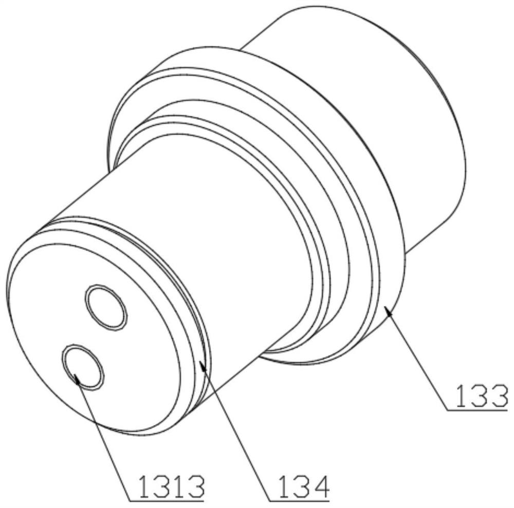
[0059] Specifically, the rotation shaft is rotatably arranged in the first hinge hole 111 , the second hinge hole 122 and the third hinge hole 123 ;

[0060] Specifically, the inner ring of the bearing pad 14 is sleeved outside the rotating shaft, and the inner ring of the bearing pad 14 is an interference fit ...


PUM


Abstract

The invention relates to a rotating joint which comprises a first joint body, a second joint body, a rotating shaft, a bearing bush and a plurality of bearings. The inner ring of the bearing bush is in interference fit with the rotating shaft. The outer ring of the bearing bush is in interference fit with a first hinge hole. The two ends of the rotating shaft are symmetrically sleeved with the plurality of bearings. According to the rotating joint, the bearing bush and the rotating shaft are in micro-interference fit, when a machine operates abnormally (for example, when the machine bears an impact load or the bearing is invalid and jammed), an interaction force exists between the rotating shaft and the bearing bush, and when the interaction force can destroy the micro-interference fit between the rotating shaft and the bearing bush, the rotating shaft and the bearing bush can rotate relatively, and sliding friction occurs between the two. At the moment, the internal stress is converted into the form of kinetic energy and friction heat, the force acting between the rotating shaft and the bearing bush is buffered, the effect of protecting the machine joints is achieved, and the problems of damage and even breakage caused by sudden increase of the stress at the robot joint positions due to bearing failure or jamming or impact load bearing are solved.

Description

technical field [0001] The invention relates to the technical field of industrial robots, in particular to a rotary joint and a robot. Background technique [0002] Palletizing robots are already a relatively mature product in industry, and their application scenarios and cases are numerous. However, my country's industrial robot industry started late, and the technical support is relatively not so perfect, especially in the field of large-scale heavy-duty robots. The country is basically monopolized by foreign industrial robot industry giants such as ABB, Yaskawa, KUKA, and FANUC. In order to promote the development of the domestic robot industry, the state also strongly supports and continuously introduces favorable policies. [0003] The rotating joint of the robot is an important part of the robot. The existing robot joints will cause the stress on the rotating joint of the robot to increase suddenly after the bearing fails, gets stuck, or is subjected to an impact load...

Claims


Application Information

Patent Timeline
Patent Type & Authority Applications(China)
IPC IPC(8): B25J17/00B25J17/02B65G61/00
CPCB25J17/00B25J17/02B65G61/00
Inventor 蔡国庆杨医华周文李子龙
Owner 伯朗特机器人股份有限公司
Learn More