
Batch current transformer calibration auxiliary device

A technology of current transformers and auxiliary devices, which is applied in the direction of measuring devices, measuring electrical variables, instruments, etc., can solve the problems of time-consuming and labor-intensive construction efficiency of secondary wiring, and achieve the effects of saving secondary wiring time, reasonable structure, and convenient use

Pending Publication Date: 2021-03-23
国网新疆电力有限公司营销服务中心 +1
View PDF0 Cites 1 Cited by
  • Summary
  • Abstract
  • Description
  • Claims
  • Application Information

AI Technical Summary

Problems solved by technology

[0003] The invention provides a batch current transformer verification auxiliary device, which overcomes the deficiencies of the above-mentioned prior art, and can effectively solve the problems of time-consuming and labor-intensive and low construction efficiency existing in the existing current transformer verification secondary wiring

Method used


Image

  • Batch current transformer calibration auxiliary device
  • Batch current transformer calibration auxiliary device
  • Batch current transformer calibration auxiliary device

Examples


Embodiment Construction

[0017] The present invention is not limited by the following examples, and specific implementation methods can be determined according to the technical solutions of the present invention and actual conditions.

[0018] In the present invention, for the convenience of description, the description of the relative positional relationship of each component is based on the description attached to the description. figure 1 For example, the positional relationship of front, rear, top, bottom, left, right, etc. is determined according to the layout direction of the drawings in the description.

[0019] Below in conjunction with embodiment and accompanying drawing, the present invention will be further described:

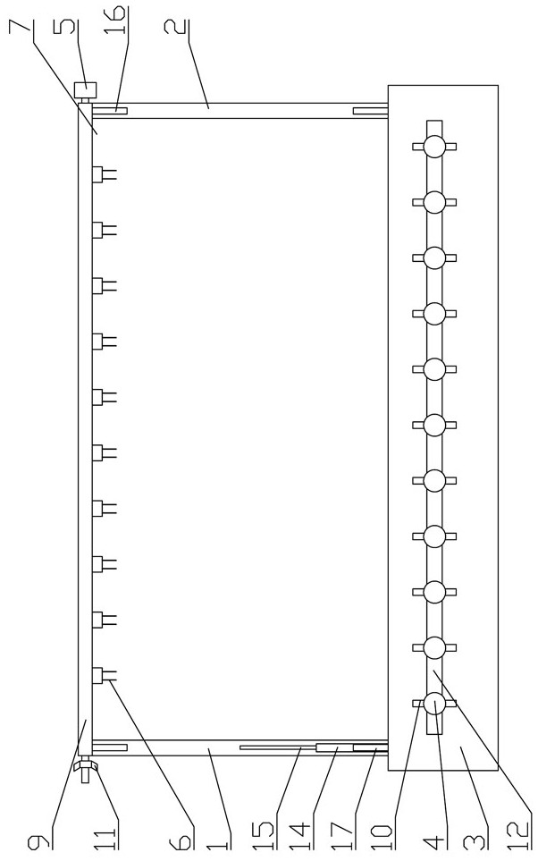
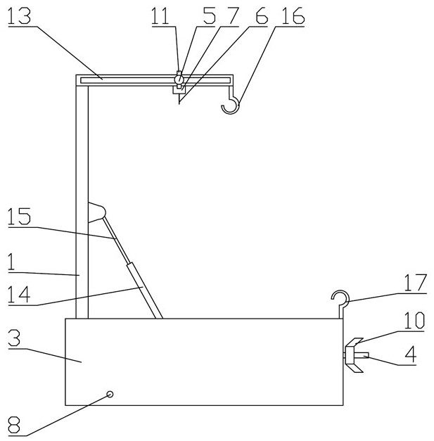
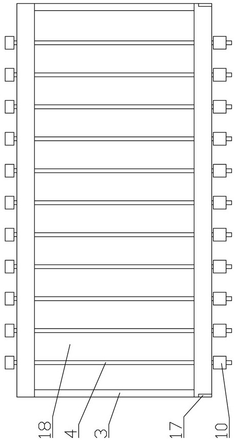
[0020] as attached figure 1 , 2 , 3, the batch current transformer verification auxiliary device includes a conduction mechanism, a left support rod 1, a right support rod 2, a separation rod 4 and a box 3 with an upward opening, and the left and right sides between the fr...


PUM


Abstract

The invention relates to the technical field of current transformers, in particular to a batch current transformer calibration auxiliary device, which comprises a conduction mechanism, a left supporting rod, a right supporting rod, separation rods and a box body with an upward opening. The at least two separation rods are arranged between the front side and the rear side of the box body at intervals in the left-right direction, the right supporting rod is hinged to the right end of the rear portion of the inner side of the bottom plate of the box body, and the conduction mechanism is fixedly installed at the upper ends of the left supporting rod and the right supporting rod. The device is reasonable and compact in structure and convenient to use. Current transformers of the same batch areseparated by arranging the separation rods, junction boxes and conduction binding posts are installed on suspension rods at the corresponding positions of the current transformers, the conduction binding posts can make contact with the corresponding current transformers by pressing a supporting frame downwards, batch verification can be achieved, the secondary wiring time is saved, and the characteristics of safety, labor saving, simplicity, convenience and high efficiency are achieved.

Description

technical field [0001] The invention relates to the technical field of current transformers, and relates to a verification auxiliary device for batch current transformers. Background technique [0002] When the existing low-voltage current transformer is manually verified, the secondary wiring needs to be operated by operators. The secondary wiring of a current transformer is divided into current incoming and outgoing lines. The current incoming and outgoing lines correspond to the low-voltage current transformer verification platform. The location is connected for verification. During the verification, due to the large number of current transformers, operators need to frequently connect and remove them, and the efficiency is low. Contents of the invention [0003] The invention provides a batch current transformer verification auxiliary device, which overcomes the above-mentioned deficiencies in the prior art, and can effectively solve the problems of time-consuming and l...

Claims


Application Information

Patent Timeline
Patent Type & Authority Applications(China)
IPC IPC(8): G01R35/02
CPCG01R35/02
Inventor 段志尚胡玉军王璐刘超刘文忠朱新颜姜昆周慧琼谭成伟师虹章晓洁
Owner 国网新疆电力有限公司营销服务中心
Learn More