Diamagnetic three-dimensional gear tripod head

A technology of pan/tilt and gear, which is applied in the direction of machine platform/support, supporting machine, mechanical equipment, etc. It can solve the problems of not meeting high precision requirements, angle offset, and low wear resistance of gears, so as to improve the accuracy of use , the effect of small adjustment stroke and high adjustment accuracy

Active Publication Date: 2021-03-23
深圳市荣者光电科技发展有限公司
View PDF7 Cites 0 Cited by
  • Summary
  • Abstract
  • Description
  • Claims
  • Application Information

AI Technical Summary

Problems solved by technology

[0003] The currently known pan / tilts not only have low precision but also low wear resistance, which do not meet the strict requirements of the instrument on the accuracy and wear resistance of the pan / tilt. At the same time, most of the three-dimensional pan / tilts on the market rely on the swing pan / tilt to connect the instrument to adjust the angle. Swing to the angle and turn the handle to lock, it is difficult to see the object when you want to observe the object at a long distance, and there will be an angle offset when turning the handle to lock, so that the high-precision requirements cannot be met. The gears made of the three-dimensional gear head have low wear resistance , the design space is not in place and there is the possibility of idling. At the same time, the raw materials of the existing three-dimensional gear heads on the market usually contain materials such as iron, cobalt and nickel. Some instruments installed on the head cannot be close to iron, cobalt and nickel When materials such as iron, cobalt and nickel are close to materials such as iron, cobalt and nickel, the instrument will be inaccurate in long-distance observation. For this reason, we have proposed a three-dimensional gear platform involving antimagnetic to solve the above problems

Method used


Image

  • Diamagnetic three-dimensional gear tripod head
  • Diamagnetic three-dimensional gear tripod head
  • Diamagnetic three-dimensional gear tripod head

Examples


Embodiment

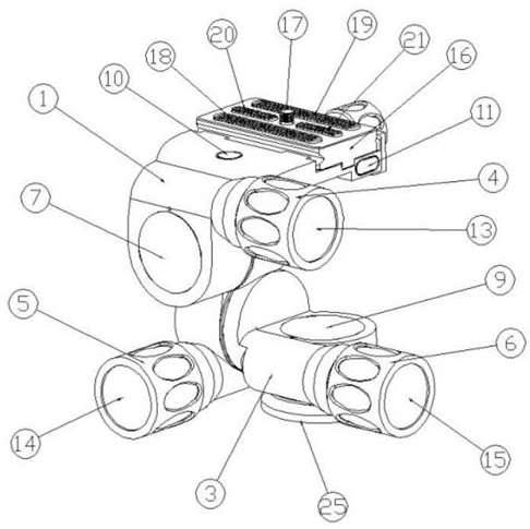
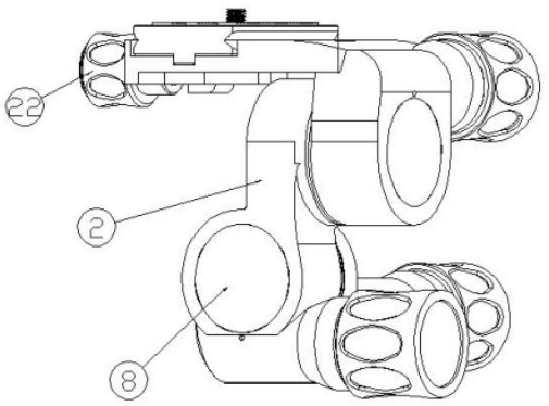
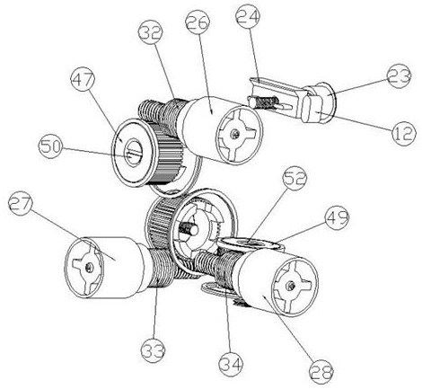
[0024] Such as Figure 1-Figure 6The shown antimagnetic three-dimensional gear platform includes a first housing 1, a second housing 2 and a third housing 3, and the inner sides of the first housing 1, the second housing 2 and the third housing 3 are respectively The first dial 7, the second dial 8 and the third dial 9 are fixedly installed, and the first turbine upper cover is respectively connected to the first dial 7, the second dial 8 and the third dial 9 47. The second turbine upper cover 48 and the third turbine upper cover 49, the first turbine upper cover 47, the second turbine upper cover 48 and the third turbine upper cover 49 are respectively connected with the first turbine 44 and the second turbine 45 and the third worm wheel 46, and the inside of the first worm wheel 44, the second worm wheel 45 and the third worm wheel 46 are threadedly connected with a first lock worm screw 50, a second lock worm screw 51 and a third lock worm screw 52, ​​the first The lock tu...


PUM


Abstract

The invention discloses a diamagnetic three-dimensional gear tripod head which comprises a first shell, a second shell and a third shell. According to the diamagnetic three-dimensional gear tripod head, through cooperation of a first worm, a second worm, a third worm, a first worm gear, a second worm gear and a third worm gear, the worm gears are engaged with the worms during use, so that the response between devices is more direct; meanwhile, the single-time adjusting stroke is smaller, and therefore the adjusting precision of the diamagnetic three-dimensional gear tripod head is larger, theproblems that in existing tripod head equipment, during adjusting, the angle deviates, and the requirement for high precision cannot be met easily are avoided, and meanwhile the phenomena of idling and unsmooth use are also avoided; and meanwhile, the first shell, the second shell and the third shell of the diamagnetic three-dimensional gear tripod head are all made of copper, the influence of a magnetic field cannot be generated and received in the use process, and therefore the problem of generating influences on use of part of instruments is avoided, and the use accuracy of the diamagneticthree-dimensional gear tripod head is improved.

Description

technical field [0001] The invention belongs to the technical field of mechanical pan-tilts, in particular to antimagnetic three-dimensional gear pan-tilts. Background technique [0002] The pan / tilt is a support device for installing and fixing the camera. It is divided into two types: fixed and electric. After reaching the best working posture, just lock the adjustment mechanism. [0003] The currently known gimbals not only have low precision but also low wear resistance, which do not meet the strict requirements of the instrument on the gimbal accuracy and wear resistance. Swing to the angle and turn the handle to lock. When you want to observe objects from a long distance, it is difficult to swing to see the object. When turning the handle to lock, there will be an angle offset, which cannot meet the high-precision requirements. The gears made by the three-dimensional gear head have low wear resistance. , the design space is not in place and there is the possibility o...

Claims


Application Information

Patent Timeline
Patent Type & Authority Applications(China)
IPC IPC(8): F16M11/04F16M11/08F16M11/10F16M11/18
CPCF16M11/043F16M11/08F16M11/10F16M11/18
Inventor 吴波陈月发
Owner 深圳市荣者光电科技发展有限公司
Why Eureka
Try Eureka