Vehicle steering lamp control method, device and equipment

A control method and turn signal technology, which is applied to vehicle parts, signal devices, transportation and packaging, etc., can solve problems such as traffic accidents, and achieve the effects of improving driving safety, improving user experience, and facilitating use

Active Publication Date: 2021-03-23
BYD CO LTD +1
View PDF6 Cites 0 Cited by
  • Summary
  • Abstract
  • Description
  • Claims
  • Application Information

AI Technical Summary

Problems solved by technology

[0003] Based on the above turn signal system, the driver usually turns on or off the turn signal manually when the vehicle is turning. However, there will be situations where the driver forgets to turn on the turn signal due to negligence or fear of trouble, which will easily lead to traffic accidents.

Method used


Image

  • Vehicle steering lamp control method, device and equipment
  • Vehicle steering lamp control method, device and equipment
  • Vehicle steering lamp control method, device and equipment

Examples


Embodiment Construction

[0035] Embodiments of the present application are described in detail below, examples of which are shown in the drawings, wherein the same or similar reference numerals denote the same or similar elements or elements having the same or similar functions throughout. The embodiments described below by referring to the figures are exemplary, and are intended to explain the present application, and should not be construed as limiting the present application.

[0036] The vehicle turn signal control method, device and equipment according to the embodiments of the present application will be described below with reference to the accompanying drawings.

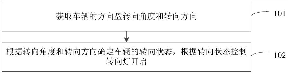
[0037] figure 1 It is a schematic flowchart of a method for controlling a vehicle turn signal provided in the embodiment of the present application, as shown in figure 1 As shown, the method includes:

[0038] Step 101, acquire the steering angle and steering direction of the vehicle's steering wheel.

[0039] In this embodiment, ...


PUM


Abstract

The invention provides a vehicle steering lamp control method, device and equipment, wherein the method comprises the steps: obtaining the steering angle and steering direction of a steering wheel ofa vehicle; and determining the steering state of the vehicle according to the steering angle and the steering direction, and controlling the turn-on of the steering lamp according to the steering state.

Description

technical field [0001] The present application relates to the technical field of vehicle control, in particular to a method, device and equipment for controlling a turn signal of a vehicle. Background technique [0002] The current vehicle turn signal system is usually composed of a body control module, a combination light switch and a turn signal. The state of the turn signal switch in the light combination switch is monitored by the body control module, and the turn signal is controlled to turn on or off according to the state of the turn signal switch. [0003] Based on the above-mentioned turn signal system, the driver usually turns on or off the turn signal manually when the vehicle is turning. However, there will be situations where the driver forgets to turn on the turn signal due to negligence or fear of trouble, which will easily lead to traffic accidents. Contents of the invention [0004] This application aims to solve one of the technical problems in the relate...

Claims


Application Information

Patent Timeline
IPC IPC(8): B60Q1/34
CPCB60Q1/346
Inventor 曾华邓启明
Owner BYD CO LTD
Why Eureka
Try Eureka