Clamping and positioning device

A technology of positioning device and positioning pin, which is applied in the field of tooling processing, can solve the problems of waste of space, complex structure of measurement station, and low measurement efficiency, and achieve the effects of high measurement efficiency, simple and reliable structure, and high space utilization rate

Pending Publication Date: 2021-03-19
SAIC GENERAL MOTORS +1
View PDF0 Cites 0 Cited by
  • Summary
  • Abstract
  • Description
  • Claims
  • Application Information

AI Technical Summary

Problems solved by technology

[0002] Cylinder bores and crankshaft bores are key product control features. Therefore, after the cylinder bores and crankshaft bores are processed, 100% online measurement of the cylinder bores and crankshaft bores is performed according to the process planning requirements. Due to the measuring station fixture and cylinder bore / crank bore measurement Due to the structural limitations of the head, the measurement of the cylinder bore and the crankshaft bore is divided into two measurement stations for measurement, which not only requires the arrangement of two sets of measurement and positioning clamping devices, but also requires more space to accommodate the two sets of fixtures, and the measurement of the cylinder The hole and the crankshaft hole are sequentially measured separately, resulting in a complex structure of the measuring station, waste of space, and low measurement efficiency

Method used


Image

  • Clamping and positioning device
  • Clamping and positioning device
  • Clamping and positioning device

Examples


Embodiment Construction

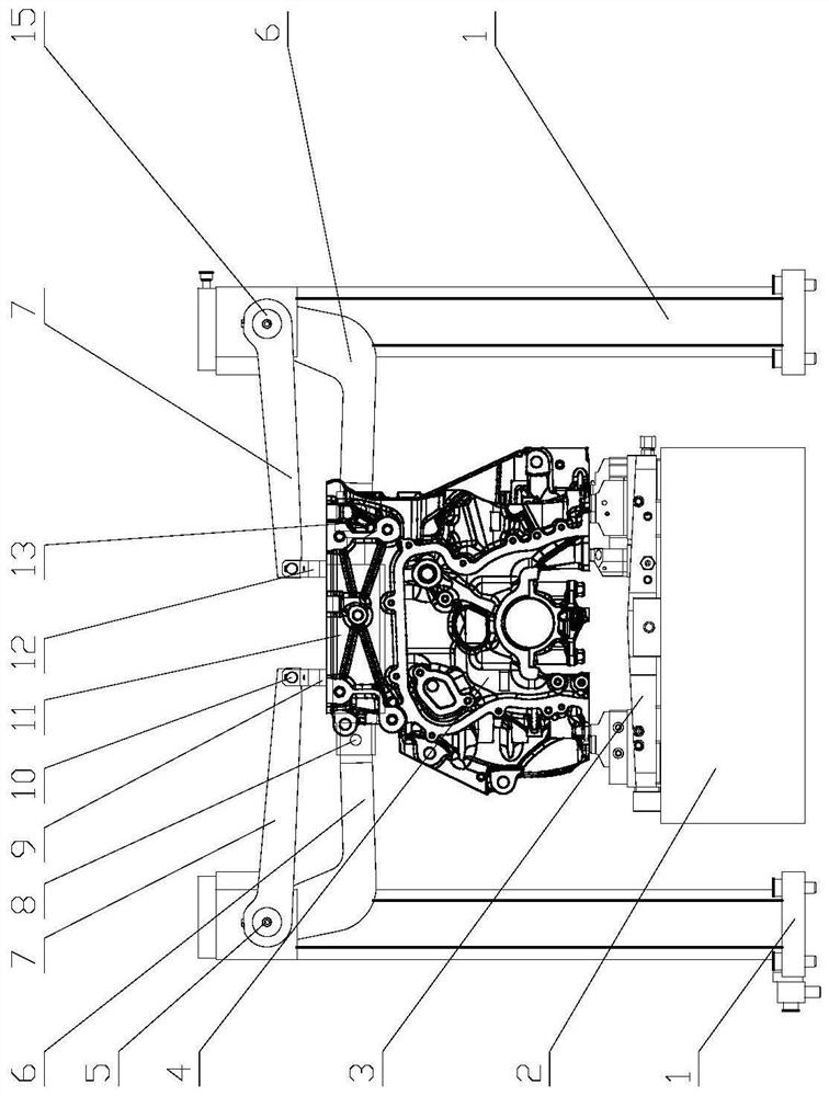
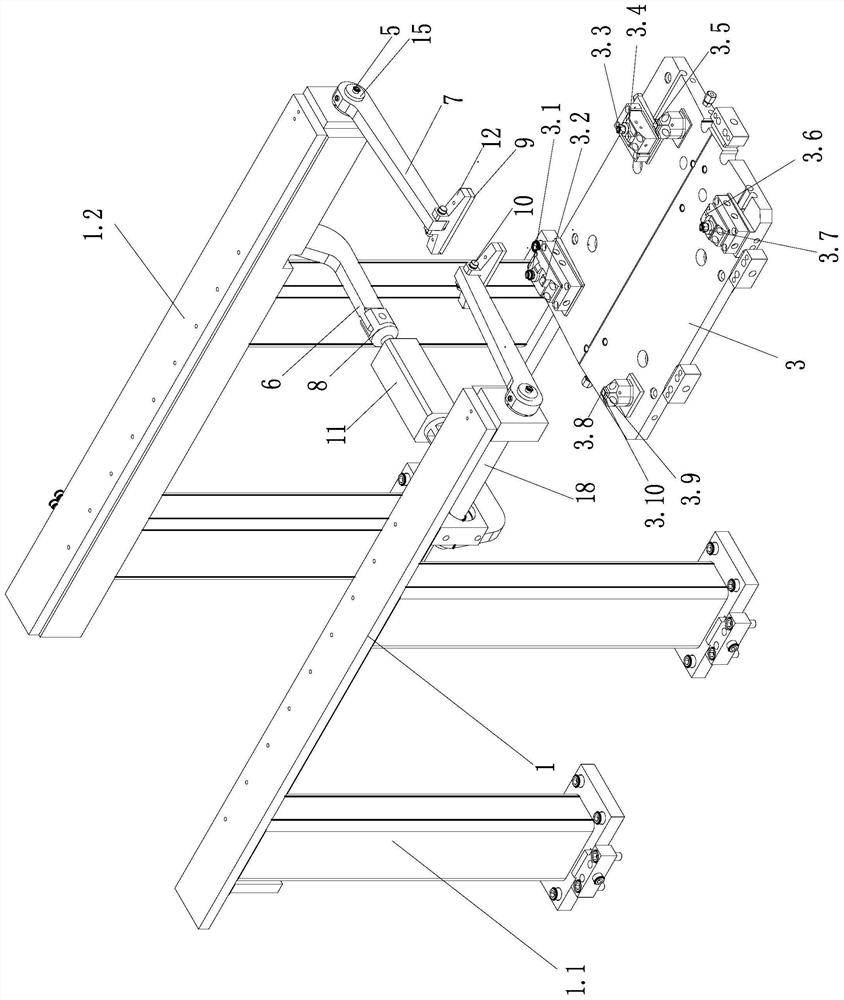
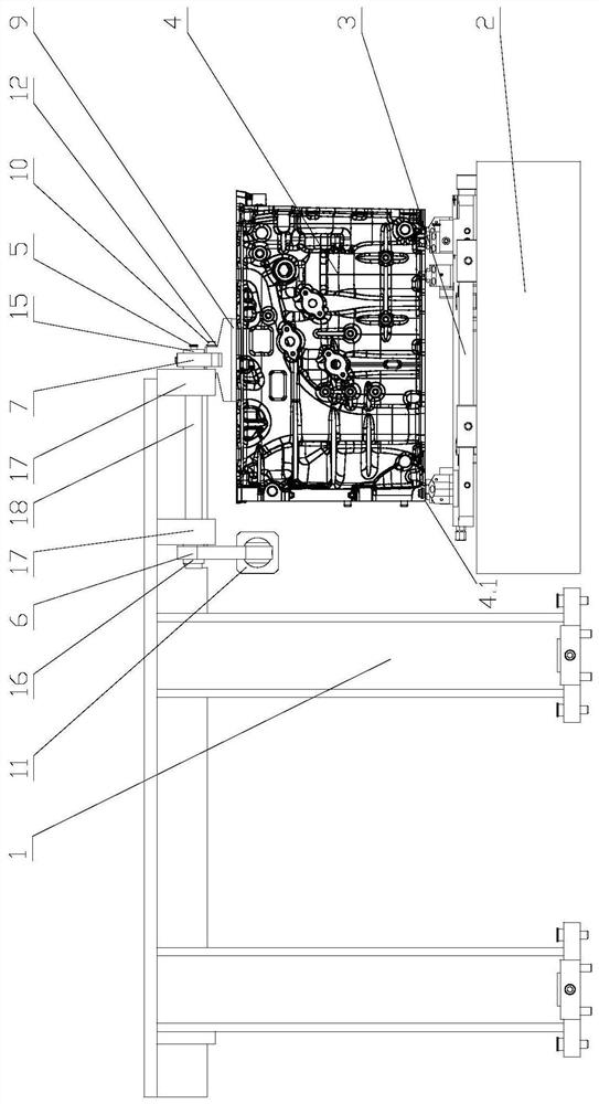
[0035] In order to make the purpose, technical solution and advantages of the present invention clearer, the following will further describe the public implementation manners of the present invention in detail with reference to the accompanying drawings.

[0036] In describing the present invention, it is to be understood that the terms "center", "longitudinal", "transverse", "length", "upper", "lower", "front", "rear", "left", " The orientation or positional relationship indicated by "right", "vertical", "horizontal", "top", "bottom", "inner", "outer", "clockwise", "counterclockwise" etc. is based on the The orientation or positional relationship is only for the convenience of describing the present invention and simplifying the description, but does not indicate or imply that the device or element referred to must have a specific orientation, be constructed and operated in a specific orientation, and therefore cannot be construed as limiting the present invention .

[0037]...


PUM


Abstract

The invention relates to the field of machining, in particular to a clamping and positioning device which comprises a supporting frame. The supporting frame comprises four supporting stand columns with supports distributed in two columns and supporting plates arranged side by side, and the supporting plates are perpendicularly fixed to the top ends of the two columns of supporting stand columns; connecting rod pressing assemblies capable of pressing a workpiece are symmetrically installed on the two supporting plates respectively, a base is arranged in the center of the supporting frame, and apositioning device for positioning the bottom of the workpiece is arranged on the base; and the connecting rod pressing assemblies and the positioning device are combined to form a workpiece clampingdevice. The clamping and positioning device is simple and reliable in structure, reasonable in space arrangement, high in space utilization rate and high in measurement efficiency.

Description

technical field [0001] The invention relates to the field of tooling processing, in particular to a clamping and positioning device. Background technique [0002] Cylinder bores and crankshaft bores are key product control features. Therefore, after the cylinder bores and crankshaft bores are processed, 100% online measurement of the cylinder bores and crankshaft bores is performed according to the process planning requirements. Due to the measuring station fixture and cylinder bore / crank bore measurement Due to the structural limitations of the head, the measurement of the cylinder bore and the crankshaft bore is divided into two measurement stations for measurement, which not only requires the arrangement of two sets of measurement and positioning clamping devices, but also requires more space to accommodate the two sets of fixtures, and the measurement of the cylinder The hole and the crankshaft hole are sequentially measured separately, resulting in complex structure of ...

Claims


Application Information

Patent Timeline
Patent Type & Authority Applications(China)
IPC IPC(8): B25B11/00G01L11/00
CPCB25B11/00G01L11/00
Inventor 吕昆仑闵信来
Owner SAIC GENERAL MOTORS
Why Eureka
Try Eureka