
Pump body and ventricular assistance system

A pump body and chamber technology, applied in the field of pump body and ventricular assist system, can solve the problems affecting the service life and reliability of the pump body, blood damage, etc.

Active Publication Date: 2021-03-19
SHENZHEN CORE MEDICAL TECH CO LTD
View PDF6 Cites 1 Cited by
  • Summary
  • Abstract
  • Description
  • Claims
  • Application Information

AI Technical Summary

Problems solved by technology

[0002] The pump body can drive the fluid medium to flow through the impeller set inside it. For the current magnetic levitation pump body, the impeller often collides with the cavity wall of the pump body during operation and wears out. As a key component, the impeller directly affects The service life and reliability of the pump body, especially the blood pump, the friction between the impeller and the cavity wall of the pump body will cause damage to the blood

Method used


Image

  • Pump body and ventricular assistance system
  • Pump body and ventricular assistance system

Examples


Embodiment Construction

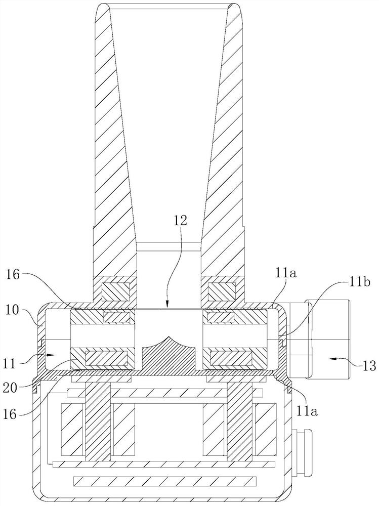
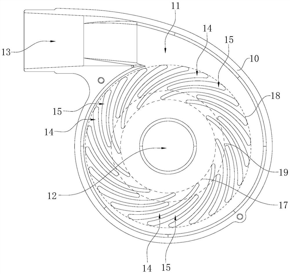
[0028] Embodiments of the present application are described in detail below, and examples of the embodiments are shown in the drawings, wherein the same or similar reference numerals denote the same or similar elements or elements having the same or similar functions throughout. Attached below by reference figure 1 and figure 2 The described embodiments are exemplary and are intended to explain the application and not to be construed as limiting the application.

[0029] In the description of the present application, it should be understood that the terms "length", "width", "upper", "lower", "front", "rear", "left", "right", "vertical", The orientation or positional relationship indicated by "horizontal", "top", "bottom", "inner", "outer", etc. are based on the orientation or positional relationship shown in the drawings, and are only for the convenience of describing the application and simplifying the description, rather than Nothing to indicate or imply that a referenced...


PUM


Abstract

The invention belongs to the technical field of medical instruments, and particularly relates to a pump body and a ventricular assistance system. The pump body comprises a pump shell and an impeller,wherein the pump shell forms a cavity and is provided with a liquid inlet, and hydraulic bearings are formed in the two cavity walls of the cavity and provided with a plurality of first dynamic pressure grooves and second dynamic pressure grooves; the first dynamic pressure grooves and the second dynamic pressure grooves are alternately distributed around the central axis of the liquid inlet, thefirst dynamic pressure grooves are longer than the second dynamic pressure grooves, the ends, close to the central axis of the liquid inlet, of the first dynamic pressure grooves are located on a first circle; and the ends, far from the central axis of the liquid inlet, of the first dynamic pressure grooves are located on a second circle; the ends, close to the central axis of the liquid inlet, ofthe second dynamic pressure grooves are located on a third circle; the circle centers of the first circle, the second circle and the third circle are located on the central axis of the liquid inlet;and the radius of the third circle is more than that of the first circle and less than that of the second circle. The impeller of the pump body is low in abrasion rate and high in use reliability.

Description

technical field [0001] The application belongs to the technical field of medical devices, and in particular relates to a pump body and a ventricular assist system. Background technique [0002] The pump body can drive the fluid medium to flow through the impeller set inside it. For the current magnetic levitation pump body, the impeller often collides with the cavity wall of the pump body during operation and wears out. As a key component, the impeller directly affects The service life and reliability of the pump body, especially the blood pump, the friction between the impeller and the cavity wall of the pump body will also cause damage to the blood. Contents of the invention [0003] The purpose of the embodiments of the present application is to provide a pump body with low impeller wear rate and high service reliability. [0004] In order to achieve the above object, the technical scheme adopted by the application is: [0005] The first aspect: provide a pump body, t...

Claims


Application Information

Patent Timeline
IPC IPC(8): A61M60/216A61M60/232A61M60/804A61M60/81A61M60/818
Inventor 余顺周
Owner SHENZHEN CORE MEDICAL TECH CO LTD
Learn More