A cable continuity test system

A technology of on-off testing and cables, which is applied in the field of cable on-off testing systems, can solve the problems of inconvenient wire placement, poor fixing effect of wire ends, poor protection effect, etc., to achieve convenient storage, prolong service life, and increase use functions Effect

Active Publication Date: 2022-05-27
WEIHAI OCEAN VOCATIONAL COLLEGE
View PDF12 Cites 2 Cited by
  • Summary
  • Abstract
  • Description
  • Claims
  • Application Information

AI Technical Summary

Problems solved by technology

[0005] In order to solve the above technical problems, the present invention provides a cable continuity test system to solve the inconvenience of placing redundant wires, poor protection effect and poor fixation effect on the end of the wire in the existing cable continuity test system The problem

Method used


Image

  • A cable continuity test system
  • A cable continuity test system
  • A cable continuity test system

Examples


Embodiment

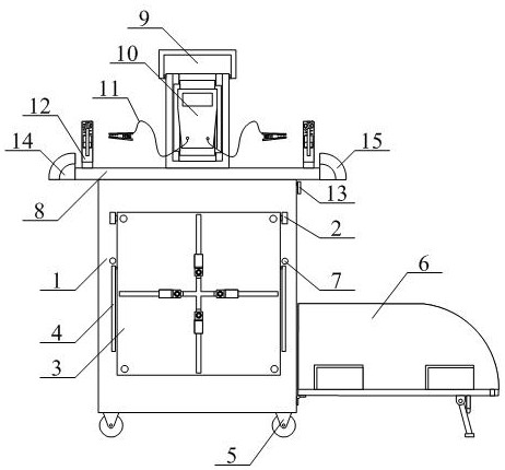
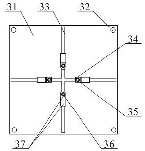
[0033] as attached figure 1 and attached figure 2As shown, a cable continuity test system includes a housing 1, an ear plate 2, a wire placement frame structure 3, a support rod 4, a moving wheel 5, a tool placement frame structure 6, a positioning hole 7, a workbench 8, and a work protection frame Structure 9, multimeter 10, test pen 11, wire end fixing frame structure 12, baffle 13, wire support frame 14 and arc groove 15, the lug plate 2 is welded on the left and right sides of the upper front end of the shell 1 respectively; The wire placement frame structure 3 is installed on the inner lower part of the ear plate 2; the support rods 4 are respectively arranged on the left and right sides of the wire placement frame structure 3; the moving wheels 5 are respectively bolted to the lower part of the housing 1 Four corner positions; the tool placement rack structure 6 is installed on the right side of the casing 1; the positioning holes 7 are respectively opened on the left ...


PUM


Abstract

The invention provides a cable on-off testing system, which includes a housing, an ear plate, a wire placement frame structure, a support rod, a moving wheel, a tool placement frame structure, a positioning hole, a workbench, a work protection frame structure, a multimeter, test pens, and wires. The end fixing frame structure, the baffle plate, the wire support frame and the arc groove, the ear plates are respectively welded on the left and right sides of the upper part of the front end of the shell; the wire placement frame structure is installed on the inner lower part of the ear plate; The supporting rods are respectively arranged on the left and right sides of the wire placement frame structure. The beneficial effects of the present invention are: through the setting of the mounting plate, the support column and the U-shaped frame, the redundant wires are placed on the upper part of the mounting plate or wound on the inner side of the U-shaped frame, which is conducive to conveniently winding the redundant part of the wires on the U-shaped frame. The inner side of the type frame is convenient for the staff to detect the longer wires and increase the use function of the equipment.

Description

technical field [0001] The invention belongs to the technical field of wire detection, and in particular relates to a cable continuity test system. Background technique [0002] Multi-core instrument cables include communication instrument cables and testing instrument cables. This type of cable is suitable for various river and sea ships to transmit signals and can be used as a connecting line for marine instruments and control equipment. When the wires that have not been used for a long time are reused, the wires need to be connected. Conduct path inspection to prevent damage to the inner side of the wire, which cannot be used normally. The cable with damaged insulation layer needs to be tested to see if it can be used normally, and the copper wire in the damaged part should be tested. [0003] However, the existing cable continuity test system also has the problems of inconvenient placement of redundant wires, poor protection effect and poor fixation effect on the ends of...

Claims


Application Information

Patent Timeline
Patent Type & Authority Patents(China)
IPC IPC(8): G01R31/54G01R31/58G01R1/02G01R1/04
CPCG01R31/54G01R31/58G01R1/02G01R1/04G01R1/0408
Inventor 胡彩霞
Owner WEIHAI OCEAN VOCATIONAL COLLEGE
Why Eureka
Try Eureka