
Method for simulating downburst by coupling wall surface jet flow and boundary layer wind tunnel of multi-blade wing grid

A multi-blade, boundary layer technology, applied in the field of wind tunnel simulation tests, can solve the problem of inability to effectively simulate the spatial distribution characteristics of downbursts, the inability to effectively simulate the time-varying characteristics of downbursts, and the inability to effectively simulate downbursts And other issues

Active Publication Date: 2021-03-16
CHONGQING UNIV
View PDF8 Cites 6 Cited by
  • Summary
  • Abstract
  • Description
  • Claims
  • Application Information

AI Technical Summary

Problems solved by technology

Although the first device can generate the downburst outflow wind profile, it cannot effectively simulate the time-varying characteristics of the wind speed after the downburst is fully developed and cannot effectively simulate the vortex structure of the downburst outflow leading edge rolling up; the second Although this device can simulate the time-varying characteristics of the downburst wind speed and the vortex structure after the airflow hits the ground, it cannot effectively simulate the spatial distribution characteristics of the downburst at any deflector rotation angle.

Method used


Image

  • Method for simulating downburst by coupling wall surface jet flow and boundary layer wind tunnel of multi-blade wing grid
  • Method for simulating downburst by coupling wall surface jet flow and boundary layer wind tunnel of multi-blade wing grid
  • Method for simulating downburst by coupling wall surface jet flow and boundary layer wind tunnel of multi-blade wing grid

Examples


Embodiment Construction

[0033] The present invention will be further described below in conjunction with the accompanying drawings and specific embodiments, so that those skilled in the art can better understand the present invention and implement it, but the examples given are not intended to limit the present invention.

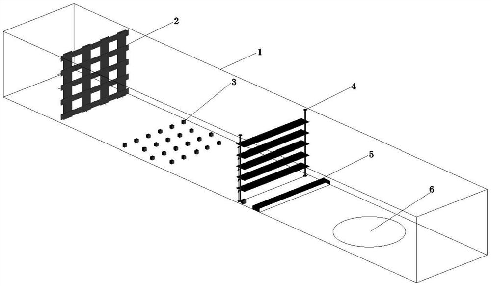
[0034] In this embodiment, the method for simulating the downburst in the boundary layer wind tunnel coupling the wall jet flow and the multi-blade wing grid is: open the axial flow fan 16 of the wall jet device 5 to obtain a stable jet wind field, and adjust the air outlet of the wall jet device 5 Adjust the angle of the plate 24, thereby changing the spatial characteristic distribution of the jet wind field, so that the maximum radial wind speed of the jet wind field appears at the set height; at the same time, the wind tunnel fan is turned on to form a set flow velocity in the wind tunnel flow channel 1 background wind field; coupling the jet wind field and the background wind f...


PUM


Abstract

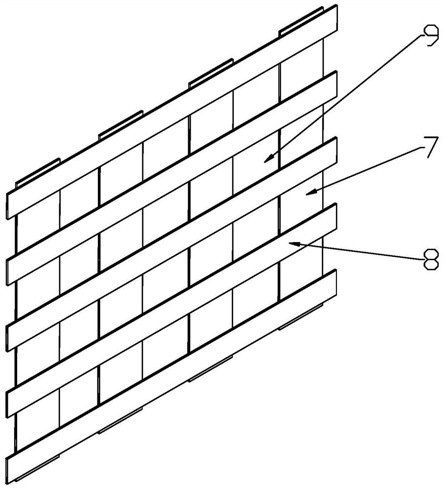
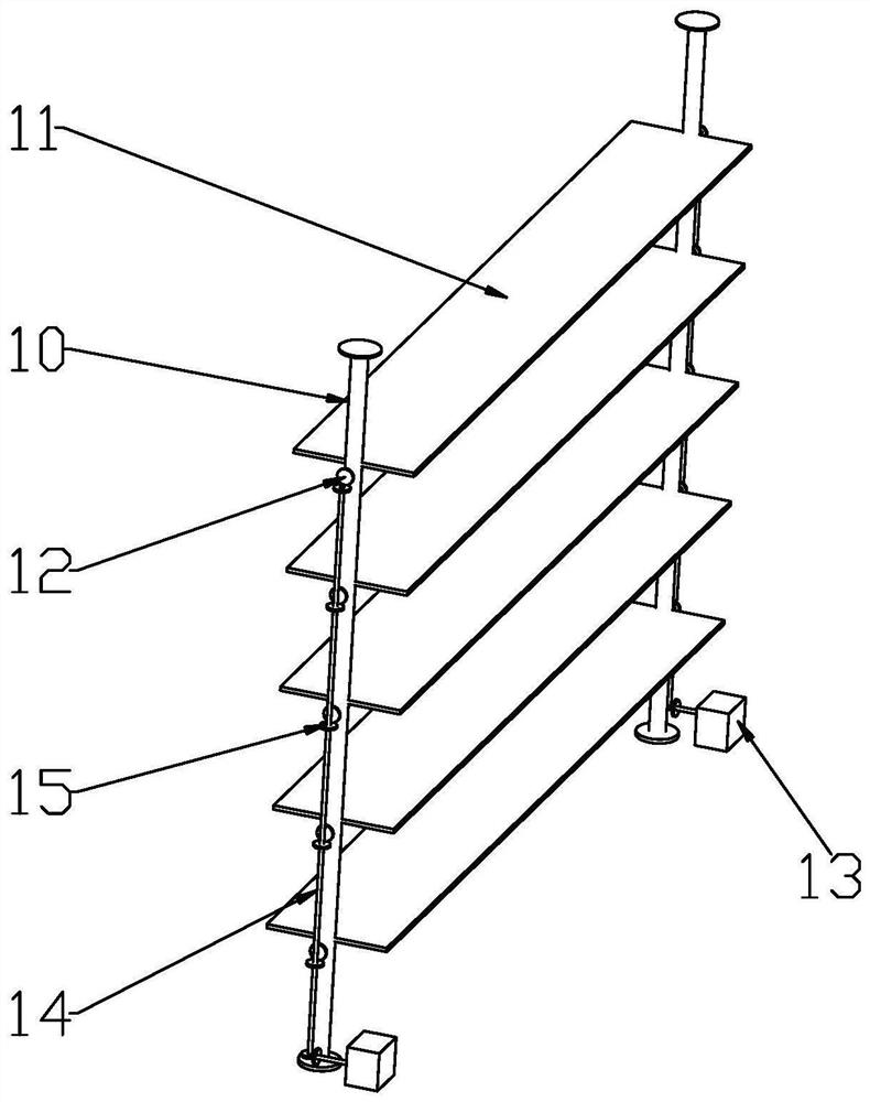
The invention discloses a method for simulating downburst by coupling wall surface jet flow and a boundary layer wind tunnel of a multi-blade wing grid, which comprises the steps of starting an axialflow fan of a wall surface jet flow device to obtain a jet flow wind field, adjusting the height of an air outlet of the wall surface jet flow device and the angle of an air outlet adjusting plate soas to change the spatial characteristic distribution of the jet flow wind field, and enabling the maximum radial wind speed of the jet flow wind field to appear at a set height; starting a wind tunnelfan at the same time, and forming a background wind field with the set flow speed in a wind tunnel flow channel; coupling the jet flow wind field and the background wind field, and obtaining a downburst outflow wind field with set spatial characteristic distribution; and adjusting the angle of a guide plate of the guide device to change along with time according to a set rule so as to enable thespatial characteristic distribution of the background wind field to change along with time, enabling the flow field characteristic of the downburst outflow wind field to change along with time, and simulating the abrupt change characteristic of the downburst outflow wind field changing along with time. Space characteristics of downburst outflow air development areas can be simulated, and time-varying unsteady characteristics and vortex area development characteristics of downburst outflow air can also be simulated.

Description

technical field [0001] The invention belongs to the technical field of wind tunnel simulation tests, in particular to a method for simulating downburst flow in a boundary layer wind tunnel coupling wall jet flow and multi-blade wing grids. Background technique [0002] Against the background of the global climate deterioration year by year, downbursts occur frequently, causing serious damage to structures such as buildings, public facilities, and transmission tower systems within their radius of action. The measured results show that the wind field characteristics of downbursts are significantly different from those of typhoons, tornadoes and other wind disasters. Therefore, there is a unique way to simulate the wind field of downbursts in wind tunnel tests. [0003] The physical simulation of downbursts in the field of wind engineering is divided into two categories, one is to simulate the entire process of development and change of downbursts, and the other is only to simu...

Claims


Application Information

Patent Timeline
Patent Type & Authority Applications(China)
IPC IPC(8): G01M9/06G01M9/04
CPCG01M9/04G01M9/065
Inventor 闫渤文袁养金马晨燕舒臻孺杨庆山曹曙阳
Owner CHONGQING UNIV
Learn More