
A low-temperature heat pump water jet jet enthalpy increasing system and its control method

A technology of air injection to increase enthalpy and control methods, which is applied in heat pumps, heating methods, air conditioning systems, etc., can solve problems such as complex logic, uncontrolled hidden dangers, poor consistency, etc., and achieve the effect of small switching and stable and reliable adjustment process

Active Publication Date: 2022-08-02
GUANDONG GIWEE TECH CO LTD
View PDF0 Cites 0 Cited by
  • Summary
  • Abstract
  • Description
  • Claims
  • Application Information

AI Technical Summary

Problems solved by technology

The disadvantages of this exhaust temperature protection logic are:
[0003] 1. After reaching the set exhaust temperature, the exhaust temperature of the unit will always fluctuate with the frequent adjustment of the valve opening (the temperature curve is jagged), which is not conducive to the stable control operation of the unit;
[0004] 2. The setting of the fixed valve opening does not have the applicability of various models, and each model needs to re-match the fixed valve opening; if the consistency of the production process in the workshop is poor, the fixed valve opening is only applicable to Units that are consistent with the model used to match them have uncontrolled hidden dangers
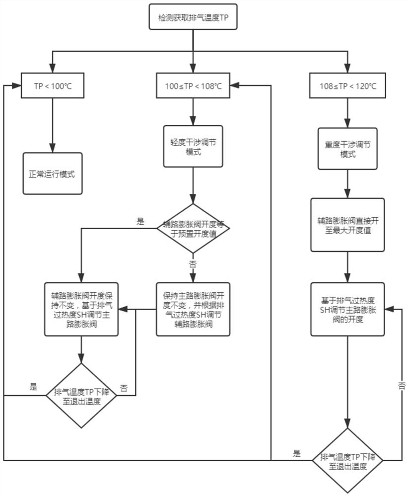
[0005] The technical reasons that lead to the problem: 1. For the jet booster model, it is necessary to control two electronic expansion valves in the main circuit and the auxiliary circuit at the same time, and the control logic is complicated; 2. In the low-temperature heating condition, the exhaust temperature of the unit reaches a higher setting When the temperature is fixed, the control logic of the opening of the main and auxiliary valves is different from the normal operation control logic of the unit, and it is more complicated to formulate the logic of the unit's intelligent exhaust control

Method used


Image

  • A low-temperature heat pump water jet jet enthalpy increasing system and its control method
  • A low-temperature heat pump water jet jet enthalpy increasing system and its control method
  • A low-temperature heat pump water jet jet enthalpy increasing system and its control method

Examples


Embodiment Construction

[0033] In order to facilitate understanding of the present invention, the present invention will be described more fully below with reference to the accompanying drawings. The preferred embodiments of the invention are shown in the accompanying drawings. However, the present invention may be embodied in many different forms and is not limited to the embodiments described herein. These embodiments are provided so that a thorough and complete understanding of the present disclosure will be provided.

[0034] see attached figure 1 As shown, in this embodiment, a jet enthalpy increase system for a low temperature heat pump water machine includes a compressor, a four-way valve, an indoor heat exchanger, an outdoor heat exchanger and a water-side heat exchanger, wherein the four-way valve includes There are four interfaces. The four ports of the four-way valve are respectively connected with the output port of the compressor, one end of the indoor heat exchanger, the input port o...


PUM


Abstract

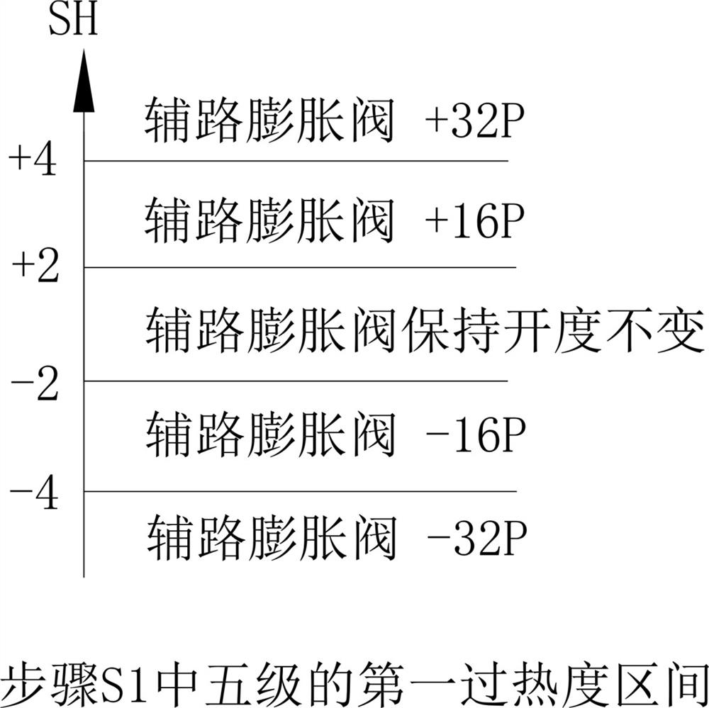
The invention discloses a jet enthalpy increasing system for a low-temperature heat pump water machine, comprising a compressor, a four-way valve, an indoor heat exchanger, an outdoor heat exchanger and a water side heat exchanger. The outdoor heat exchanger exchanges heat with the water side. The main path expansion valve is arranged on the flow path pipeline between the heat exchangers; it also includes an auxiliary path pipeline, one end of which extends through the outdoor heat exchanger and is bypassed to the flow between the outdoor heat exchanger and the main path expansion valve. The other end of the auxiliary pipeline is connected to the input port of the compressor, and the auxiliary pipeline is provided with an auxiliary expansion valve between the outdoor heat exchanger and the bypass position; An exhaust gas temperature sensor for real-time detection and acquisition of exhaust gas temperature TP is provided on the flow path pipeline between the through valves, so that under low temperature conditions, it is determined whether to perform interference adjustment on the system based on the detected exhaust gas temperature TP. , wherein, when the system needs to be interfered and adjusted, the opening degrees of the main circuit expansion valve and the auxiliary circuit expansion valve are correspondingly adjusted based on the exhaust gas temperature TP obtained by detection and the calculated exhaust gas superheat degree SH.

Description

technical field [0001] The invention relates to the technical field of heat pump air conditioning systems, in particular to a low temperature heat pump water machine jet enthalpy increasing system and a control method thereof. Background technique [0002] When the existing low-temperature air source heat pump (chiller) unit operates under the conditions of low ambient temperature and high water temperature, the exhaust temperature of the unit is likely to be too high (TP≥108°C) under normal logic adjustment. The exhaust protection logic intervenes to reduce the exhaust temperature when the unit is running. The conventional solution is to force the unit to adjust to a fixed valve opening after the unit reaches the set exhaust temperature. After the exhaust temperature decreases, the normal adjustment logic is restored and normal adjustment is restored. After the logic, the exhaust temperature will be too high again, and then forced adjustment is performed, and this cycle is ...

Claims


Application Information

Patent Timeline
Patent Type & Authority Patents(China)
IPC IPC(8): F25B13/00F25B30/02F25B41/385F25B49/02F24F5/00F24F11/65F24F11/84
CPCF25B13/00F25B30/02F25B49/02F24F5/001F24F11/65F24F11/84
Inventor 陈永鑫芦哲鑫刘华栋
Owner GUANDONG GIWEE TECH CO LTD
Learn More