Full-automatic solder paste printing machine for printed circuit board circuit

A technology for printed circuit boards and solder paste printers, applied in the directions of printed circuits, printed circuit manufacturing, printed circuit secondary processing, etc., can solve the problems of inconsistent thickness of circuit boards, reduced work efficiency, and wasted time.

Inactive Publication Date: 2021-03-16
深圳利朋技术研发有限公司
View PDF0 Cites 0 Cited by
  • Summary
  • Abstract
  • Description
  • Claims
  • Application Information

AI Technical Summary

Problems solved by technology

[0003] The fully automatic solder paste printing machine in the prior art needs to fix the circuit board before the printing operation. The fixing method in the prior art is generally to place the circuit board on the printing positioning table, and use clamping blocks to fix it. Limit fixing, although this fixing method can fix the circuit board on the positioning table relatively easily, but because the thickness of the circuit board itself is not uniform, it cannot further fix the circuit boards of different thicknesses, and it is easy to perform printing operations When there is a phenomenon of positioning deviation, resulting in a decline in the yield of the circuit board
[0004] When the automatic solder paste printing machine is working, it is necessary to use the grid plate to print the solder paste and the top of the corresponding PCB board. After repeated use, the surface of the grid plate will be blocked due to the small aperture of the grid plate. In the prior art, the grid plate is generally disassembled, rinsed after disassembly, and then put back the grid plate after rinsing. In this process, a lot of time is wasted, and it is relatively difficult to use. inconvenient
[0005] After the solder paste printing operation on the circuit board, the circuit board needs to be discharged. Since the circuit board is auxiliary fixed before the circuit board is printed in the prior art, the discharge operation still needs to manually release the circuit board. Fix it and take it out manually, and then put the circuit board into the transfer table for the next step of placement operation, which reduces the work efficiency

Method used


Image

  • Full-automatic solder paste printing machine for printed circuit board circuit
  • Full-automatic solder paste printing machine for printed circuit board circuit
  • Full-automatic solder paste printing machine for printed circuit board circuit

Examples


Embodiment Construction

[0032] The following will clearly and completely describe the technical solutions in the embodiments of the present invention with reference to the accompanying drawings in the embodiments of the present invention. Obviously, the described embodiments are only some, not all, embodiments of the present invention. Based on the embodiments of the present invention, all other embodiments obtained by persons of ordinary skill in the art without making creative efforts belong to the protection scope of the present invention.

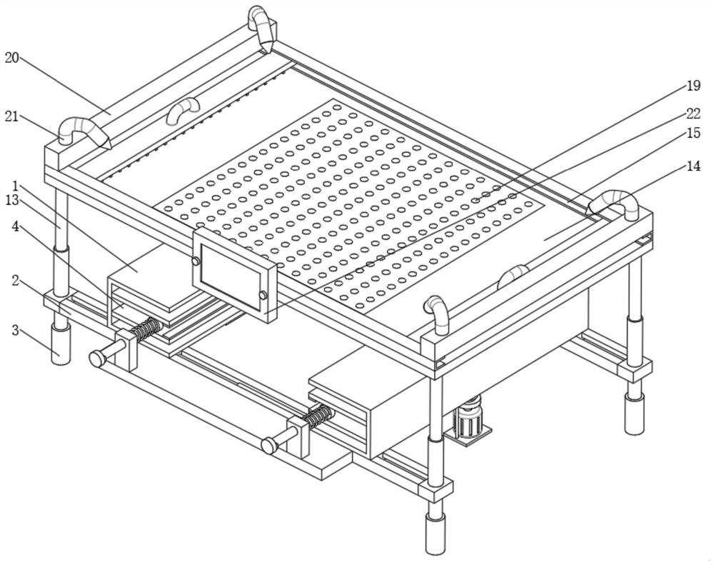
[0033] see Figure 1-9 , a fully automatic solder paste printing machine for printed circuit board circuits and a circuit printing method thereof, comprising a frame 1, the number of the frames 1 is two, and the inner surfaces of the two frames 1 are each provided with two movable plates 4 The relatively close ends of the two movable plates 4 are fixedly connected with buffer springs 6 positioned on the left and right sides between the two movable plates 4, an...


PUM


Abstract

The invention relates to the technical field of circuit board printing, and discloses a full-automatic solder paste printing machine for a printed circuit board circuit. The full-automatic solder paste printing machine comprises two machine frames, and two movable plates are arranged on the inner side surfaces of the two machine frames; and buffer springs located at the left side and the right side between the two movable plates are fixedly connected to the ends, close to each other, of the two movable plates. According to the full-automatic solder paste printing machine, the movable plates and the machine frames are internally sleeved with threaded rods in a threaded manner, main motors are arranged at the bottom ends of the threaded rods, and when circuit boards with different thicknesses need to be fixed, the main motors can be started to drive the threaded rods at the top end to rotate, the thread directions of the outer side faces of the threaded rods are opposite, and the two groups of movable plates can be driven by the threaded rods to relatively get close to or get away from each other, so that a circuit board is clamped; and meanwhile, the circuit board can be clamped bybuffer plates positioned between the two groups of movable plates, so that the circuit boards with different thicknesses can be fixed in an auxiliary manner.

Description

technical field [0001] The invention relates to the technical field of circuit board printing, in particular to a fully automatic solder paste printing machine for printed circuit board circuits Background technique [0002] Modern solder paste printing machines generally consist of mechanisms such as plate loading, solder paste addition, embossing, and circuit board delivery. Its working principle is: first fix the circuit board to be printed on the printing positioning table, and then use the left and right scrapers of the printing machine to print the solder paste or red glue on the corresponding pad through the steel mesh. The transfer table is input to the placement machine for automatic placement. [0003] The fully automatic solder paste printing machine in the prior art needs to fix the circuit board before the printing operation. The fixing method in the prior art is generally to place the circuit board on the printing positioning table, and use clamping blocks to ...

Claims


Application Information

Patent Timeline
IPC IPC(8): B41F15/08B41F15/14B41F15/26B41F35/00H05K3/12H05K3/22H05K3/26
CPCB41F15/08B41F15/14B41F15/26B41F35/005H05K3/1225H05K3/225H05K3/26H05K2203/15
Inventor 不公告发明人
Owner 深圳利朋技术研发有限公司
Why Eureka
Try Eureka