
Workpiece clamping device for laser engraving machine machining

A technology for a laser engraving machine and a clamping device, applied in the field of laser engraving machines, can solve problems such as affecting subsequent value, inconvenient placement and fixing, and defects in workpiece engraving patterns, achieving simple and convenient clamping and fixing operations, improving clamping applicability, The effect of increasing friction

Inactive Publication Date: 2021-03-16
芜湖韩大防伪科技有限公司
View PDF0 Cites 0 Cited by
  • Summary
  • Abstract
  • Description
  • Claims
  • Application Information

AI Technical Summary

Problems solved by technology

[0004] Aiming at the deficiencies of the prior art, the present invention provides a workpiece clamping device for laser engraving machining, which solves the problem that it is always inconvenient to place and fix when engraving is required on irregular objects, which affects the advancement of subsequent engraving links, and When the laser engraving machine is engraving, if it is subjected to human impact from the outside, the workpiece in the engraving is prone to displacement, causing flaws in the engraving pattern of the workpiece, which affects the subsequent value of the problem

Method used


Image

  • Workpiece clamping device for laser engraving machine machining
  • Workpiece clamping device for laser engraving machine machining
  • Workpiece clamping device for laser engraving machine machining

Examples


Embodiment Construction

[0025] Next, the technical solutions in the embodiments of the present invention will be apparent from the embodiment of the present invention, and it is clearly described, and it is understood that the described embodiments are merely embodiments of the present invention, not all of the embodiments. Based on the embodiments of the present invention, there are all other embodiments obtained without making creative labor without making creative labor premises.

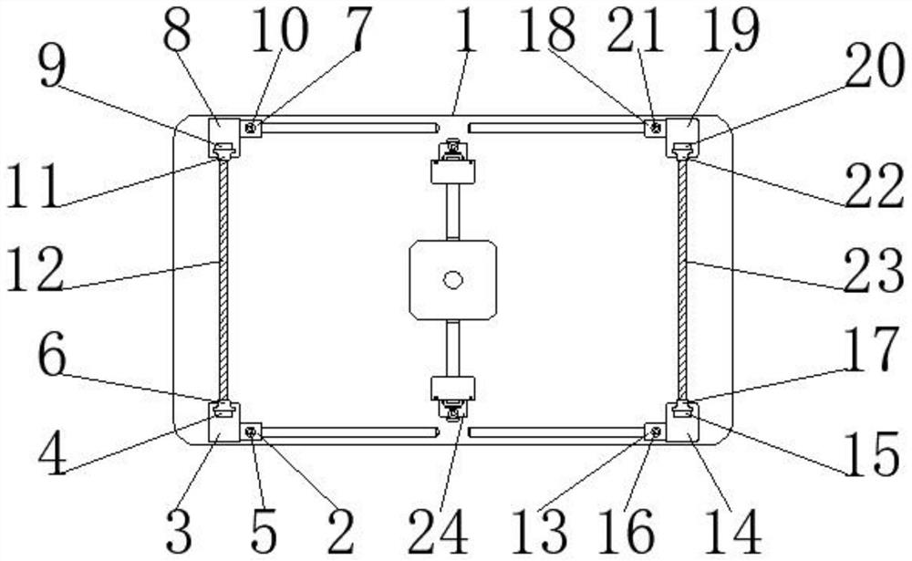
[0026] Such as Figure 1-7 As shown, the present invention provides a technical solution: a laser engraving machine machining workpiece clamping device including a table 1, a first beam with a slider 2, a first beam mount 3, a first suction block 4, The first fixing sheath 5, the first beam belt card 6, the second beam belt slider 7, the second beam mounting seat 8, the second suction block 9, the second fixing sheath 10, the second beam belt clip 11, The first bunch belt 12, the third bunch of slider 13, the third bunch of ...


PUM


Abstract

The invention relates to the technical field of laser engraving machines, and discloses a workpiece clamping device for laser engraving machine machining. The device comprises a workbench, a first strap sliding block, a first suction block, a first strap and a second strap, wherein the first strap sliding block is located below the left side of the front surface of the workbench and is slidably connected with the workbench, and the first suction block penetrates through the top end of a first strap mounting seat and is fixedly connected with the first strap mounting seat. According to the device, by arranging the first strap and the second strap and utilizing the elastic deformability of rubber, workpieces in irregular shapes can be fixed, and subsequent laser engraving machine engraving is guaranteed; by arranging the first suction block, a second suction block, a third suction block and a fourth suction block, corresponding strap clamping blocks can be adsorbed and fixed subsequently, and during need, the heights of the first strap and the second strap can be changed by sliding the corresponding strap clamping blocks so as to be suitable for fixing irregular workpieces with different height sizes, so that the fixing adaptability of the first strap and the second strap is high.

Description

Technical field [0001] The present invention relates to the field of laser engraving machine, and is specifically a laser engraving machine processing workpiece clamping device. Background technique [0002] The laser engraving machine can improve the efficiency of the engraving, which makes the surface of the carved, rapidly reduces the temperature of the carved non-metallic material, reducing the deformation and internal stress of the engraved, can be divided into CO2 according to the different laser light source. Metal laser engraving machine and fiber metal engraving machine. CO2 non-metallic laser engraving machines generally use glass laser tubes in China, and some high-end laser engraving machines use CO2 metal radiofrequency tubes. [0003] Now in the engraving link, the laser engraving machine is often used. When engraving, the planar object is easy to place the workbench. When it is necessary to engrave on irregular objects, it is always inconvenient to place fixed, aff...

Claims


Application Information

Patent Timeline
Patent Type & Authority Applications(China)
IPC IPC(8): B23K26/70B23K37/04B23K26/362
CPCB23K26/362B23K37/0435B23K26/702
Inventor 李玲芳
Owner 芜湖韩大防伪科技有限公司
Learn More