Ultrasonic dispersion device for graphene production by utilizing thermal expansion effect

A technology of ultrasonic dispersion and graphene, applied in the directions of transportation and packaging, dissolution, mixer, etc., can solve the problems of low cooling efficiency, time-consuming and laborious, and inability to adjust the cooling speed.

Inactive Publication Date: 2021-03-16
李达
View PDF0 Cites 0 Cited by
  • Summary
  • Abstract
  • Description
  • Claims
  • Application Information

AI Technical Summary

Problems solved by technology

[0005] Aiming at the deficiencies of the prior art, the present invention provides an ultrasonic dispersing device for graphene production utilizing the thermal expansion effect, which is provided with a heat dissipation block, and wraps the heat dissipation block around the rod body so that the heat dissipation block directly absorbs the heat radiation around the rod body. At the same time, by setting the heat-absorbing plate that can alternately absorb the heat on the heat-dissipating block, the advantage of keeping the temperature around the rod body constant is that the contact area between the condensation pipe and the ultrasonic vibrating rod is small, and at the same time, it cannot be adjusted according to the temperature. A good adjustment of the cooling speed will lead to a large change in the temperature around the ultrasonic vibrating rod. At the same time, the cooling efficiency is low. In addition, the existing device needs to pass air into the solution to achieve a mixing effect, which is time-consuming and labor-intensive.

Method used


Image

  • Ultrasonic dispersion device for graphene production by utilizing thermal expansion effect
  • Ultrasonic dispersion device for graphene production by utilizing thermal expansion effect
  • Ultrasonic dispersion device for graphene production by utilizing thermal expansion effect

Examples


Embodiment Construction

[0028] The technical solutions in the embodiments of the present invention will be clearly and completely described below with reference to the accompanying drawings in the embodiments of the present invention. Obviously, the described embodiments are only a part of the embodiments of the present invention, but not all of the embodiments. Based on the embodiments of the present invention, all other embodiments obtained by those of ordinary skill in the art without creative efforts shall fall within the protection scope of the present invention.

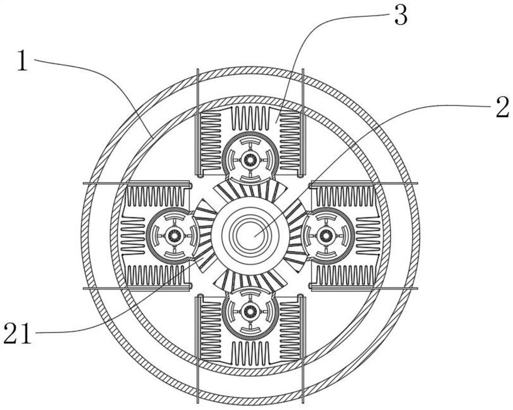
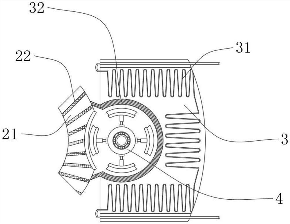
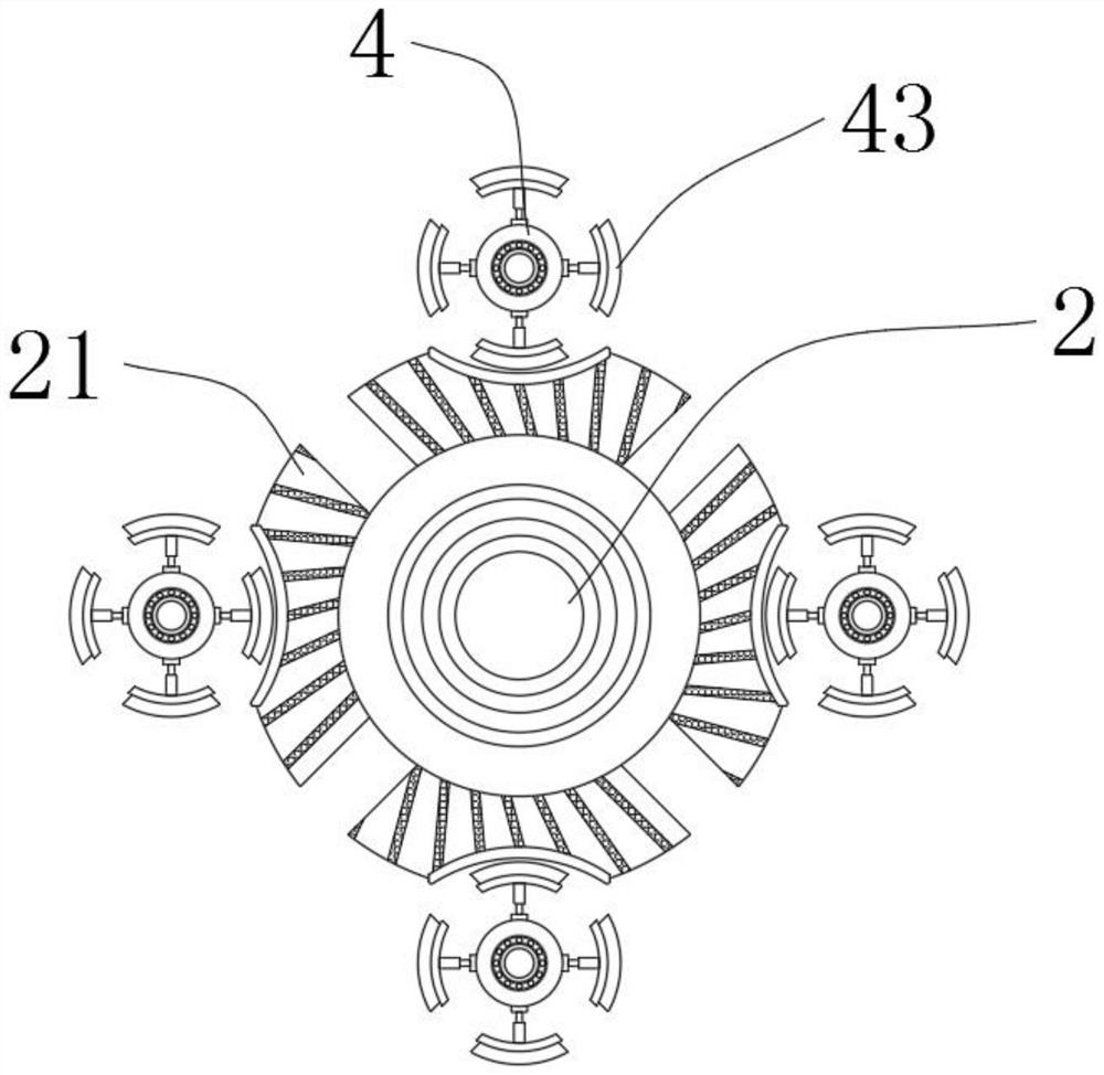
[0029] see Figure 1-6 , a kind of ultrasonic dispersing device for graphene production utilizing thermal expansion effect, comprising dispersing pipe 1, dispersing pipe 1 is composed of two concentric pipe bodies, and an interlayer is formed between the two concentric pipe bodies, and the interlayer can add cooling water, so that the cooling water further reduces the temperature in the dispersion pipe 1, the ultrasonic vibration rod ...


PUM


Abstract

The invention relates to the technical field of graphene production equipment, and discloses a graphene production ultrasonic dispersion device utilizing a thermal expansion effect, the graphene production ultrasonic dispersion device comprises a dispersion pipe, an ultrasonic vibration rod body is fixedly connected to the center of the interior of the dispersion pipe, and a heat dissipation blockis fixedly connected to the outer side wall of the ultrasonic vibration rod body; the inner side wall of the dispersion pipe is fixedly connected with a heat absorption block; the heat dissipation block is arranged on the periphery of the ultrasonic vibration rod body and wraps the ultrasonic vibration rod body inside, when the ultrasonic vibration rod body works and generates heat, the heat is directly absorbed by the heat dissipation block, the purpose of reducing the surrounding temperature of the ultrasonic vibration rod body is achieved, in addition, the contact area between the heat dissipation block and the ultrasonic vibration rod body is large, the temperature adsorption efficiency is improved, meanwhile, a heat absorption plate is further arranged on one side of the heat dissipation block, the heat absorption plate directly absorbs the temperature on the heat dissipation block, and the temperature around the ultrasonic vibration rod body is further reduced.

Description

technical field [0001] The invention relates to the technical field of graphene production equipment, in particular to an ultrasonic dispersion device for graphene production utilizing thermal expansion effect. Background technique [0002] Graphene is a carbon atom with sp 2 Hybrid orbitals form a hexagonal two-dimensional carbon nanomaterial with a honeycomb lattice. Graphene has excellent physical properties and is a new material with great development potential. Among them, graphene is difficult to disperse in liquid and easy to agglomerate , which greatly affects the application of graphene. In the prior art, for the dispersion of graphene, the ultrasonic dispersion method is usually used. Ultrasonic dispersion is to use ultrasonic waves of a specific frequency and energy to vibrate in the liquid, thereby generating cavitation. And a large number of micro-bubbles are formed. These micro-bubbles will generate huge energy on the surface during the formation and rupture p...

Claims


Application Information

Patent Timeline
Patent Type & Authority Applications(China)
IPC IPC(8): B01F11/02B01F15/06
CPCB01F31/83B01F2035/98B01F35/92
Inventor 李娜王江涛曹鹏
Owner 李达
Why Eureka
Try Eureka