
Display substrate, preparation method thereof and display device

A technology for displaying substrates and bases, which is applied in semiconductor/solid-state device manufacturing, semiconductor devices, electrical components, etc. It can solve the problems of packaging layer damage and cracks, and achieve the effect of reducing damage

Active Publication Date: 2021-03-12
BOE TECH GRP CO LTD
View PDF11 Cites 3 Cited by
  • Summary
  • Abstract
  • Description
  • Claims
  • Application Information

AI Technical Summary

Problems solved by technology

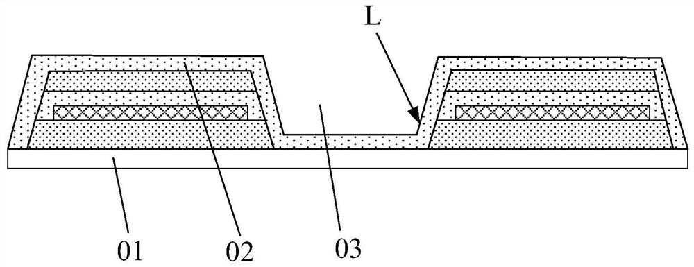
The stretchable display substrate is carried by a hard carrier such as glass during the preparation process. After the opening of the hole area is formed, the surface of the hard carrier will be exposed. When the encapsulation layer is formed, it will be formed on the hard carrier at the same time. In this way, when the hard carrier board is peeled off from the stretchable display substrate (removal process), the encapsulation layer on the hard carrier board and the encapsulation layer at the sidewall of the hole area are difficult to completely break If it is not completely disconnected, the packaging layer at the side wall of the opening in the hole area will be pulled and cracks will easily occur, which will cause damage to the packaging layer during the removal process.

Method used


Image

  • Display substrate, preparation method thereof and display device
  • Display substrate, preparation method thereof and display device
  • Display substrate, preparation method thereof and display device

Examples


Embodiment Construction

[0053] The technical solution of the present application will be further described below in conjunction with the accompanying drawings and through specific implementation methods. It should be understood that the specific embodiments described here are only used to explain the present application, but not to limit the present application.

[0054] In stretchable display panels, the way of wrinkling needs to consider the uniform distribution within a certain range to match the corresponding wiring and pixels evenly distributed. In order to achieve higher resolution (PPI), paper-cutting is often used. It is carried out by means of slotting in the panel to provide tensile properties (usually a straight or I-shaped opening). When using the kirigami process, it is found that the stretchability is limited after the slotting, and the part of the packaging structure that is in contact with the glass carrier is difficult to completely disconnect when the process is removed, and the non...


PUM


Abstract

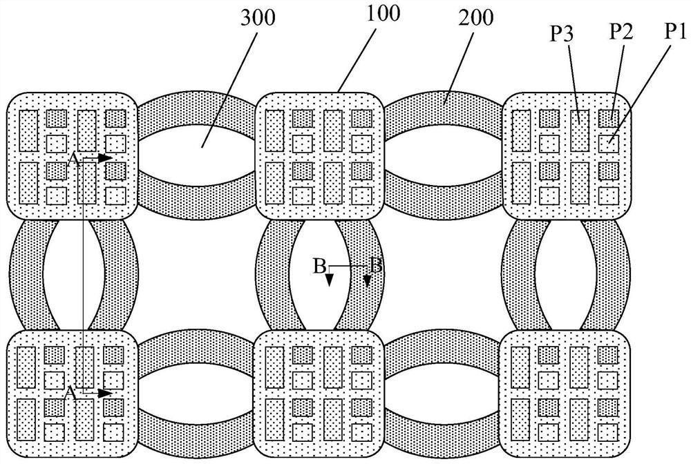
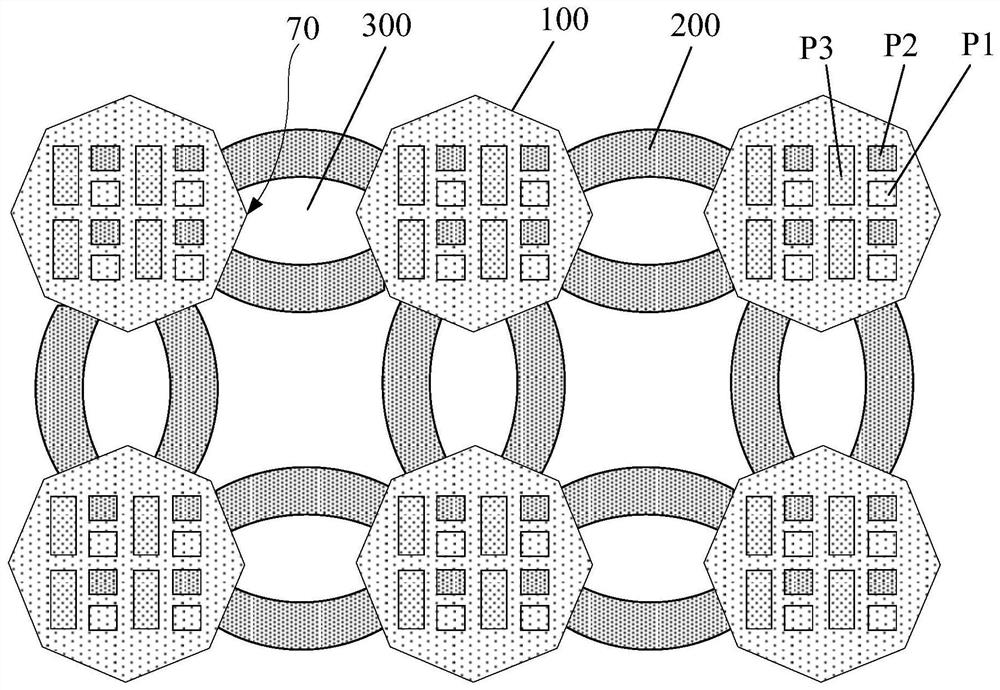
The invention discloses a display substrate, a preparation method thereof and a display device, and relates to but not limited to the technical field of display, the display substrate comprises a plurality of island areas and a plurality of hole areas which are separated from each other, and bridge areas connected with adjacent island areas; wherein the island area or / and the bridge area comprisesan edge area adjacent to the hole area; the edge area comprises a composite structure layer arranged on the substrate, a step structure is formed on the side face, facing the hole area, of the composite structure layer, and the edge area further comprises an inorganic packaging layer arranged on the composite structure layer and arranged on the step structure. The edge of the inorganic packaginglayer is located on the side face, facing the hole region, of the first step with the lowest height, and the inorganic packaging layer exposes at least part of the area of the side face of the first step. The display substrate provided by the embodiment of the invention can improve the problem of damage to the inorganic packaging layer in the taking-down process.

Description

technical field [0001] Embodiments of the present disclosure relate to, but are not limited to, the field of display technologies, and in particular, relate to a display substrate, a manufacturing method thereof, and a display device. Background technique [0002] Organic Electroluminescent Display (OLED) has gradually become the mainstream in the display field due to its low power consumption, high color saturation, wide viewing angle, thin thickness, and flexibility, and can be widely used in smart phones. Terminal products such as mobile phones, tablets, and TVs. Among them, flexible OLED products have gradually become the mainstream of OLED displays because they can meet various special structures. With the development of flexible technology, flexible display panels are gradually transitioning from bendable (Bendable) and foldable (Foldable) to elastic and flexible (Rollable), and the requirements for device flexibility are gradually increasing. [0003] In some stretc...

Claims


Application Information

Patent Timeline
Patent Type & Authority Applications(China)
IPC IPC(8): H01L27/32H01L51/00H01L51/52H01L51/56H10K99/00
CPCH10K59/12H10K77/10H10K77/111H10K50/844H10K71/00Y02E10/549H10K59/19H10K59/873H10K71/80H10K59/1201H10K59/35H10K59/124
Inventor 田宏伟牛亚男刘明李然王晶刘政
Owner BOE TECH GRP CO LTD
Learn More