Method and device for measuring track of atomic group in atomic interferometer
A technology of atom interferometer and measuring device, which is applied in the direction of measuring device, radiation measurement, particle motion recording, etc., can solve the problem of poor accuracy of atomic group trajectory measurement, and achieve the effect of high accuracy
- Summary
- Abstract
- Description
- Claims
- Application Information
AI Technical Summary
Problems solved by technology
Method used
Image
Examples
Embodiment 1
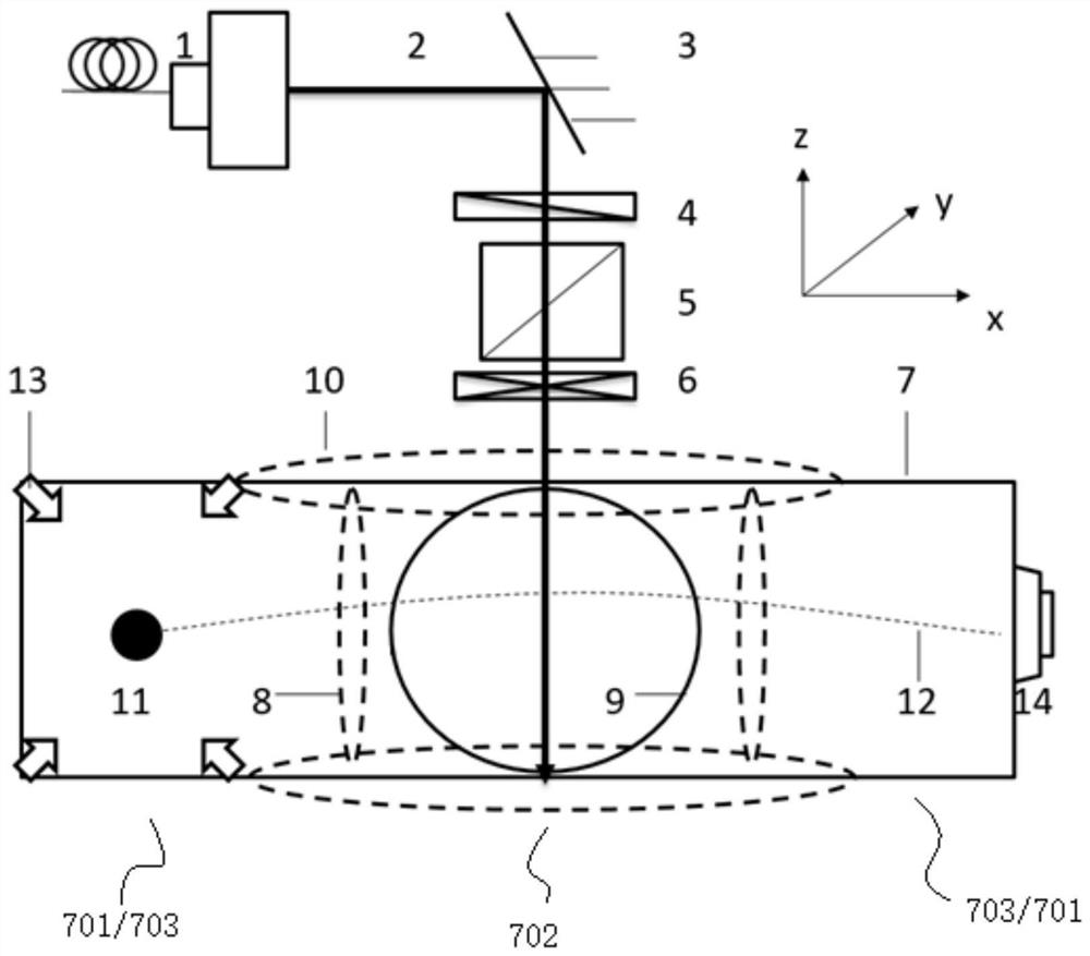
[0059] Such as figure 1 A device for measuring the orbit of atomic groups in an atomic interferometer, including an optical system composed of an atomic interferometer physical system, a co-directional Raman laser 2 and a cooling laser 13, and a circuit system composed of a photodetector and the like.
[0060] The atomic interferometer physical system includes a vacuum chamber 7 and an atom cooling chamber 701 , an atom interference chamber 702 and an atom detection chamber 703 sequentially arranged in the vacuum chamber 7 .
[0061] The atom cooling cavity 701 and the atom interference cavity 702 communicate with each other, and the atom interference cavity 702 and the atom detection cavity 703 communicate with each other.
[0062] An alkali metal releasing agent is arranged in the vacuum chamber 7 .
[0063] The magnetic field required by the magneto-optical trap is formed in the atom cooling cavity 701 through the reverse Helmholtz coil; the cooling region is formed in the...
Embodiment 2
[0070] A method for measuring the trajectory of atomic groups in an atomic interferometer, utilizing the measuring device for the trajectory of atomic groups in an atomic interferometer described in Embodiment 1, comprising the following steps:
[0071] Step 1. Turn on the magneto-optical trap cooling laser, Raman laser and reverse Helmholtz coil current to preheat for at least half an hour. Heating the alkali metal release agent diffuses the alkali metal atoms into the atomic cooling chamber 701 of the vacuum chamber 7;
[0072] Step 2, turn on the current of the gradient magnetic field coil 10 in the z direction, and adjust the magnitude and direction of the current to generate a magnetic field B in the z direction z , the magnetic field B in the z direction in this step z Consists of two parts, one part is the bias magnetic field B in the z-axis direction 0 , the other part is the gradient magnetic field in the z-axis direction, and the currents of the gradient magnetic f...
Embodiment 3
[0098] Embodiment 2 is further optimized. In Embodiments 1 and 2, one end of the vacuum chamber 7 is an atom cooling chamber 701 and the other end is an atom detection chamber 703 . The atom interference chamber 702 is located between the atom cooling chamber 701 and the atom detection chamber 703 .
[0099] In this embodiment, before the alkali metal atomic groups 11 are projected along the parabolic trajectory 12, the two ends of the vacuum chamber 7 are atomic cooling chambers 701, and after the alkali metal atomic groups 11 are projected along the parabolic trajectory 12, the two ends of the vacuum chamber 7 are atom detection chambers 703.
[0100] In step 3, the reverse Helmholtz coil forms the magnetic field required by the magneto-optical trap at both ends of the vacuum chamber 7, and the cooling laser 13 emitted by the magneto-optical trap cooling laser forms a cooling region at both ends of the vacuum chamber 7 and The alkali metal atomic groups 11 in the cooling regi...
PUM
 Abstract
Description
Claims
Application Information
 - R&D
- Intellectual Property
- Life Sciences
- Materials
- Tech Scout
- Unparalleled Data Quality
- Higher Quality Content
- 60% Fewer Hallucinations
Browse by: Latest US Patents, China's latest patents, Technical Efficacy Thesaurus, Application Domain, Technology Topic, Popular Technical Reports.
© 2025 PatSnap. All rights reserved.Legal|Privacy policy|Modern Slavery Act Transparency Statement|Sitemap|About US| Contact US: help@patsnap.com


