A device for improving the combustion efficiency of a combustion chamber of a gas turbine

A combustion efficiency and gas turbine technology, which is applied in the direction of gas turbine devices, combustion chambers, continuous combustion chambers, etc., can solve the problems of inability to use fuel, low fuel utilization efficiency, and low combustion efficiency of oil-gas mixture, so as to reduce the thickness of carbon deposits and improve Combustion efficiency, the effect of high combustion efficiency

Active Publication Date: 2022-04-15
山东赛马力发电设备有限公司
View PDF8 Cites 0 Cited by
  • Summary
  • Abstract
  • Description
  • Claims
  • Application Information

AI Technical Summary

Problems solved by technology

[0004] However, the combustion efficiency of the oil-air mixture in the existing combustion chamber is low, and the fuel cannot be fully utilized, resulting in low fuel utilization efficiency

Method used


Image

  • A device for improving the combustion efficiency of a combustion chamber of a gas turbine
  • A device for improving the combustion efficiency of a combustion chamber of a gas turbine
  • A device for improving the combustion efficiency of a combustion chamber of a gas turbine

Examples


Embodiment Construction

[0034] In order to make the objects and advantages of the present invention clearer, the present invention will be further described below in conjunction with the examples; it should be understood that the specific examples described here are only for explaining the present invention, and are not intended to limit the present invention.

[0035] Preferred embodiments of the present invention are described below with reference to the accompanying drawings. Those skilled in the art should understand that these embodiments are only used to explain the technical principle of the present invention, and are not intended to limit the protection scope of the present invention.

[0036] It should be noted that, in the description of the present invention, terms such as "upper", "lower", "left", "right", "inner", "outer" and other indicated directions or positional relationships are based on the terms shown in the accompanying drawings. The direction or positional relationship shown is ...


PUM


Abstract

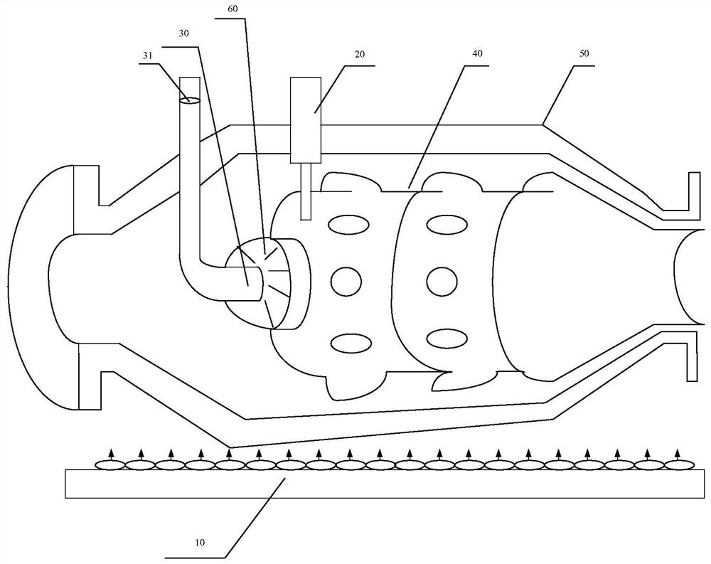
The invention relates to a compressor applied to a gas turbine. The device comprises: a compressor turbine, a casing, a flame tube, a nozzle and an ignition device. A regulating valve is arranged on the nozzle to adjust the amount of fuel ejection; the compressor turbine is provided with a The first intake valve and the second intake valve, the ultrasonic detection device emits ultrasonic waves to detect the thickness of carbon deposits on the inner wall of the flame cylinder; the central control unit communicates with the regulating valve, the first intake valve, the second intake valve and the ultrasonic The detection device is connected, and the central control unit adjusts the regulating valve, the first intake valve and the second intake valve according to the detection results of the ultrasonic detection device; when the ultrasonic detection device detects that the carbon deposit thickness on the inner wall of the flame cylinder is not within the preset thickness range , then adjust the first intake valve and the second intake valve to control the air volume entering the flame cylinder and adjust the regulating valve to control the fuel injection volume, so that the air volume and the fuel injection volume can reach the best combustion ratio, so that Improve the combustion efficiency of the combustion chamber.

Description

technical field [0001] The invention relates to the field of energy utilization, in particular to a device for improving the combustion efficiency of a combustion chamber of a gas turbine. Background technique [0002] The main function of the combustor is to mix the high-pressure air from the compressor turbine with the fuel injected by the fuel nozzle and burn it through equal pressure, convert the chemical energy stored in the fuel into heat energy, form high-temperature gas and send it to the turbine to drive the turbine to do work . [0003] The combustion chamber is composed of shell, flame tube, nozzle, vortex, ignition device and so on. The high-pressure air from the diffuser section of the compressor is divided into two streams: one stream (accounting for about 1 / 4-2 / 5) enters the front of the flame tube, mixes with the fuel sprayed from the nozzle to form an oil-air mixture, and burns after being ignited by the ignition device . The other stream (accounting for ...

Claims


Application Information

Patent Timeline
Patent Type & Authority Patents(China)
IPC IPC(8): F02C3/00F02C3/14F02C9/52F02C9/54F23R3/42
CPCF02C3/00F02C3/14F02C9/52F02C9/54F23R3/42
Inventor 殷爱军曹政坤董洪旭陈光亮侯跃艳李建勇刘玉良殷增宝
Owner 山东赛马力发电设备有限公司
Why Eureka
Try Eureka