Eureka AIR delivers breakthrough ideas for toughest innovation challenges, trusted by R&D personnel around the world.

Clip nail gun

A technology of clamping nails and gun nozzles, which is applied in the direction of nailing tools and manufacturing tools, which can solve the problems such as difficult to meet the spring and frame fixing, and achieve the effect of convenient maintenance, fewer components, and lower difficulty of assembly

Pending Publication Date: 2021-03-12
张梅凤
View PDF0 Cites 0 Cited by
  • Summary
  • Abstract
  • Description
  • Claims
  • Application Information

AI Technical Summary

Problems solved by technology

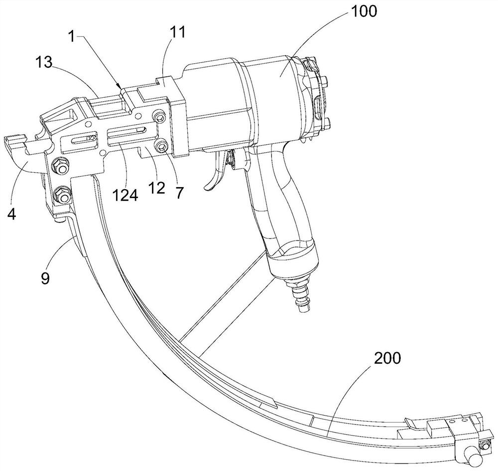
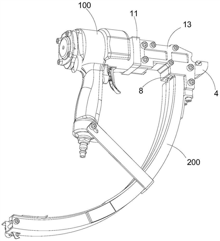
[0003] The existing method is to set the clamping nail on the spring and the frame through the clamping nail gun, and the clamping nail gun drives the push rod to push the pressing block against the clamping nail, so that the clamping nail is set on the spring and the frame On the frame, however, in the existing clamping nail gun, the stroke of the pressing block is fixed, and when the pressing block presses the clamping nail, the degree of bending of the clamping nail is fixed, so the clamping nail gun Difficult to fix springs and frames of various sizes

Method used


Image

  • Clip nail gun
  • Clip nail gun
  • Clip nail gun

Examples


Embodiment Construction

[0023] Orientation terms such as up, down, left, right, front, back, front, back, top, and bottom that are mentioned or may be mentioned in this specification are defined relative to their structures, and they are relative concepts. Therefore, it is possible to make corresponding changes according to its different positions and different usage states. Accordingly, these or other directional terms should not be construed as limiting terms.

[0024] The implementations described in the following exemplary examples do not represent all implementations consistent with the present disclosure. Rather, they are merely examples of approaches consistent with aspects of the disclosure as recited in the appended claims.

[0025] The terminology used in the present disclosure is for the purpose of describing particular embodiments only, and is not intended to limit the present disclosure. As used in this disclosure and the appended claims, the singular forms "a", "the", and "the" are in...


PUM


Abstract

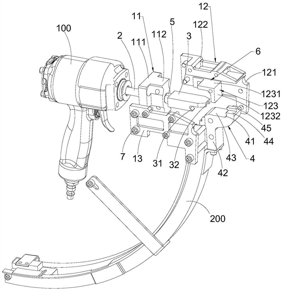
The invention discloses a clip nail gun. The clip nail gun comprises a pneumatic gun body and a nail pressing mechanism arranged at a gun mouth of the pneumatic gun body, wherein the nail pressing mechanism comprises a guide assembly, a push rod, a pressure block and a forming block; one end of the push rod extends into the pneumatic gun body which is used for driving the push rod to extend out and draw back; the other end of the push rod is connected to the pressure block; the position, opposite to the push rod, of the pressure block can be axially adjusted along the push rod; the guide assembly is fixedly arranged at the gun mouth of the pneumatic gun body for guiding the pressure block; the forming block is fixed at one end, away from the pneumatic gun body, of the guide assembly; a first arc-shaped groove is formed in one side, close to the pneumatic gun body, of the forming block; a second arc-shaped groove is formed in one side, away from the pneumatic gun body, of the pressure block; and the first arc-shaped groove and the second arc-shaped groove define a clamping space for clamping clip nails. The clip nail gun disclosed by the invention can change bending degree of the clip nails, so that the clip nails can be blocked onto springs and side frames of various dimensions, and thus, practicability of the clip nail gun is improved.

Description

technical field [0001] The invention relates to the technical field of clipping nail guns, in particular to a clipping nail gun. Background technique [0002] Spring mattress is a mattress commonly used in modern times with better performance. In the production process of spring mattresses, the connection between the springs in the bed net and the frame needs to be connected by clamping nails. [0003] The existing method is to set the clamping nail on the spring and the frame through the clamping nail gun, and the clamping nail gun drives the push rod to push the pressing block against the clamping nail, so that the clamping nail is set on the spring and the frame On the frame, however, in the existing clamping nail gun, the stroke of the pressing block is fixed, and when the pressing block presses the clamping nail, the degree of bending of the clamping nail is fixed, so the clamping nail gun Difficult to fix springs and frames of various sizes. Contents of the inventi...

Claims


Application Information

Patent Timeline
Patent Type & Authority Applications(China)
IPC IPC(8): B25C1/04
CPCB25C1/04
Inventor 张梅凤
Owner 张梅凤
Why Eureka
Eureka Blog
Learn More