
Automatic remote controller assembly line

An automatic assembly and remote control technology, which is applied in the direction of assembly machines, metal processing, metal processing equipment, etc., can solve the problems of affecting the normal use of products, low manual assembly efficiency, and large labor costs, so as to avoid finger contact with the display screen , Reduce labor cost input and improve work efficiency

Pending Publication Date: 2021-03-12
张毅 +2
View PDF1 Cites 0 Cited by
  • Summary
  • Abstract
  • Description
  • Claims
  • Application Information

AI Technical Summary

Problems solved by technology

[0002] When the remote control is assembled, it needs to go through multiple processes. In different processes, the parts in the remote control need to be assembled. At present, in most cases, the remote control is manually placed in different processes for assembly. Assembled by manipulators or directly assembled manually, the efficiency of manual assembly is low, and it is difficult to ensure the accuracy of grasping, and it is easy to take the wrong parts, especially when assembling board parts, such as display screens and circuit boards, these parts are usually In some cases, manual assembly is required, the efficiency of manual assembly is low, and the investment is large. At the same time, fingerprints or other impurities often stick to the display screen, and sometimes scratches are left on the display screen, which affects the normal use of the product.
[0003] In view of this, a remote control automatic assembly line is disclosed in the patent document with the application number 201610052165.2, which has low production efficiency and large labor costs.

Method used


Image

  • Automatic remote controller assembly line
  • Automatic remote controller assembly line
  • Automatic remote controller assembly line

Examples


Embodiment

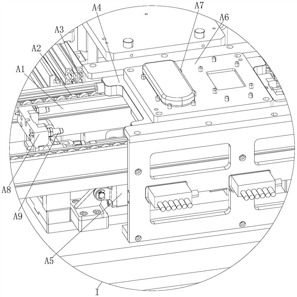
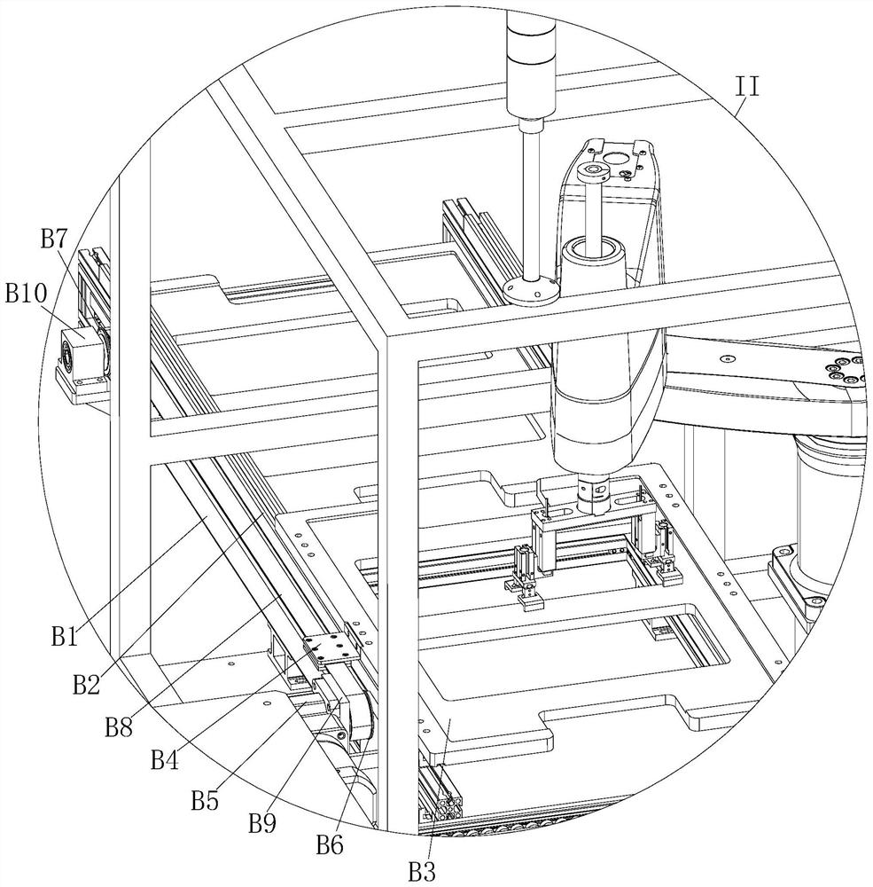
[0040] see Figure 1 to Figure 6 It should be noted that the structures, proportions, sizes, etc. shown in the drawings attached to this specification are only used to match the content disclosed in the specification, for those who are familiar with this technology to understand and read, and are not used to limit the present invention Therefore, it has no technical substantive meaning, and any modification of structure, change of proportional relationship or adjustment of size shall still fall into the within the scope covered by the technical content disclosed in the present invention. At the same time, if there are terms such as "upper", "lower", "left", "right", "middle" and "one" in this specification, they are only for the convenience of description and are not used to limit the scope of this specification. The practicable scope of the invention and the change or adjustment of its relative relationship shall also be regarded as the practicable scope of the present inven...


PUM


Abstract

The invention relates to an automatic remote controller assembly line, and belongs to the field of mechanical automation. The automatic remote controller assembly line comprises a conveying line and arack, and the conveying line is installed on the rack; the automatic remote controller assembly line is structurally characterized by further comprising a feeding device, a grabbing device and a suction cup device; and an upper shell feeding procedure, a gluing procedure, an outer cover feeding and film tearing procedure, an overturning and dust collection procedure, a liquid crystal screen feeding and wiping procedure, a conductive strip feeding and assembling procedure, a key feeding and assembling procedure, a circuit board feeding and assembling procedure, a first screw locking procedure,a spring feeding and assembling procedure, a rear cover feeding and assembling procedure, a second screw locking procedure, a battery cover feeding and assembling procedure, a labeling procedure anda product discharging procedure are sequentially arranged on the rack in the conveying direction of the conveying line.

Description

technical field [0001] The invention relates to an automatic assembly line for remote controllers, which belongs to the field of mechanical automation. Background technique [0002] When the remote control is assembled, it needs to go through multiple processes. In different processes, the parts in the remote control need to be assembled. At present, in most cases, the remote control is manually placed in different processes for assembly. Assembled by manipulators or directly assembled manually, the efficiency of manual assembly is low, and it is difficult to ensure the accuracy of grasping, and it is easy to take the wrong parts, especially when assembling board parts, such as display screens and circuit boards, these parts are usually In some cases, manual assembly is required. Manual assembly is inefficient and expensive. At the same time, fingerprints or other impurities often stick to the display screen, and sometimes scratches are left on the display screen, which affe...

Claims


Application Information

Patent Timeline
IPC IPC(8): B23P21/00
CPCB23P19/001B23P19/007B23P21/004
Inventor 张毅
Owner 张毅
Learn More