Granulation equipment for compound fertilizer production
A kind of granulation equipment and compound fertilizer technology, which is applied in the direction of fertilizer mixture, mold extrusion granulation, solid/semi-solid fertilizer, etc. It can solve the problems of non-replacement and different sizes, and achieve uniform size, high output rate, The effect of improving the pass rate
- Summary
- Abstract
- Description
- Claims
- Application Information
AI Technical Summary
Problems solved by technology
Method used
Image
Examples
Embodiment 1
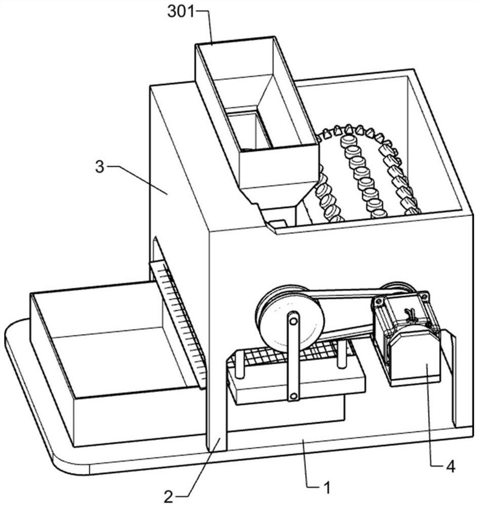
[0025] A kind of granulation equipment for compound fertilizer production, such as figure 1 As shown, it includes a bottom plate 1, supporting legs 2, a cabinet 3, a feed bin 301, a frame 4, a motor 401 and a granulation device. Four supporting legs 2 are fixedly connected to the top of the bottom plate 1, and the upper ends of the supporting legs 2 are fixed It is connected with an organic case 3, the feeding bin 301 is installed on the left upper part of the case 3, the frame 4 is fixedly connected to the right front side of the case 3, the frame 4 is fixedly connected with a motor 401, and the granulation device is rotatably connected to the case 3. The particle device is fixedly connected with the motor 401.
[0026] The staff starts the motor 401 first, then adds the compound fertilizer that has been stirred into the feed bin 301, and the motor 401 will drive the granulation device to work. At this time, the compound fertilizer will enter the granulation device along the ...
Embodiment 2
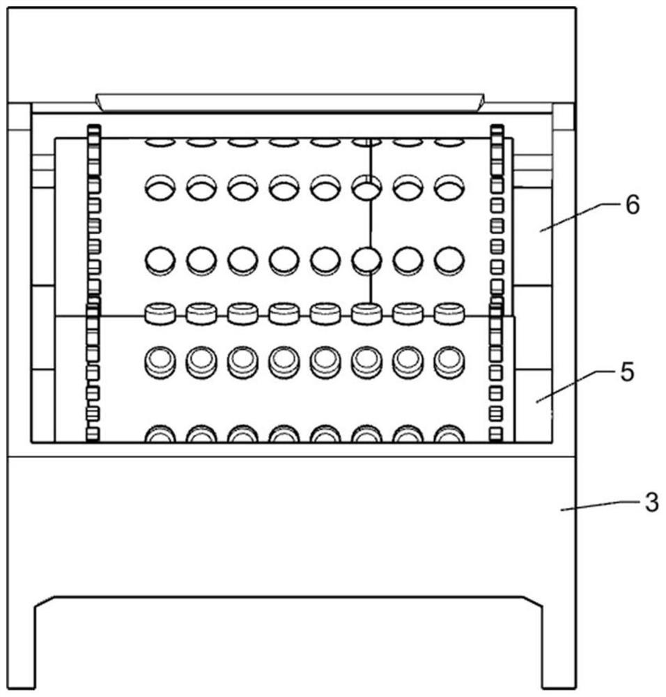
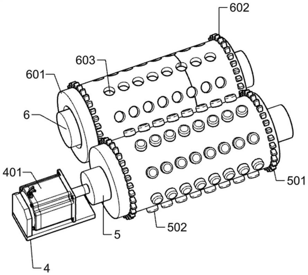
[0028] On the basis of Example 1, such as Figure 2-5 As shown, the granulation device includes a punch 5, tooth one 501, bump 502, thick shaft 6, die 601, tooth two 602, push block 603, spring 604 and top block 605, and the punch 5 is rotatably connected On the right side inside the chassis 3, the punch 5 is fixedly connected to the rear end of the output shaft of the motor 401, and the teeth 1 501 are symmetrically arranged on both ends of the outer ring of the punch 5, and several bumps 502 are arranged on the outer surface of the punch 5 , the thick shaft 6 is fixedly connected to the left side inside the chassis 3, a row of top blocks 605 is arranged on the thick shaft 6, the die 601 is rotatably connected to the thick shaft 6, and the front and rear ends of the outer surface of the die 601 are provided with a symmetrical For tooth 2 602, tooth 2 602 meshes with tooth 1 501, a small hole is provided on the die 601, and the small hole cooperates with the bump 502, and a pu...
Embodiment 3
[0031] On the basis of Example 2, such as Figure 6-8 As shown, the bottom of the feeding bin 301 is provided with a round hole 303 corresponding to the die 601 , and the size of the round hole 303 is the same as the diameter of the hole on the die 601 .
[0032] The bottom of the feed bin 301 has a round hole 303 opposite to each row of the die 601, so that the feed added to the pair of feed bins 301 will all enter the die 601, and the unprocessed feed will not be entrained into the finished product , the size and shape of the feed particles made in this way are more uniform.
[0033] The die 601 and the parts installed thereon, the punch 5 and the parts installed thereon are replaceable.
[0034] The die 601, the punch 5 and the attached parts thereon are replaceable, so that the dies can be replaced according to different requirements, thereby producing fertilizer granules of different specifications.
[0035]Also include small pulley one 7, rotating shaft 701, large pull...
PUM
 Abstract
Description
Claims
Application Information
 - R&D
- Intellectual Property
- Life Sciences
- Materials
- Tech Scout
- Unparalleled Data Quality
- Higher Quality Content
- 60% Fewer Hallucinations
Browse by: Latest US Patents, China's latest patents, Technical Efficacy Thesaurus, Application Domain, Technology Topic, Popular Technical Reports.
© 2025 PatSnap. All rights reserved.Legal|Privacy policy|Modern Slavery Act Transparency Statement|Sitemap|About US| Contact US: help@patsnap.com


