
A windproof retractable antenna structure

An antenna structure and antenna technology, applied in antennas, folded antennas, antenna components, etc., can solve problems such as performance loss, inability to guarantee absolute sealing, and influence of metal devices, so as to improve technical performance, reduce corrosion and moisture effects, The effect of improving the service life

Active Publication Date: 2022-05-17
YANTAI UNIV +1
View PDF9 Cites 0 Cited by
  • Summary
  • Abstract
  • Description
  • Claims
  • Application Information

AI Technical Summary

Problems solved by technology

For the sake of daily maintenance and replacement, most of the windshields are detachable parts, which cannot guarantee absolute sealing. In addition, the windshield needs to be opened during daily maintenance, which will cause some salt mist to still enter the inside of the windshield along with the air flow. , affecting the internal metal devices
As a passive component, the antenna is usually made of metal, which is also susceptible to salt spray, resulting in performance degradation

Method used


Image

  • A windproof retractable antenna structure
  • A windproof retractable antenna structure
  • A windproof retractable antenna structure

Examples


Embodiment 1

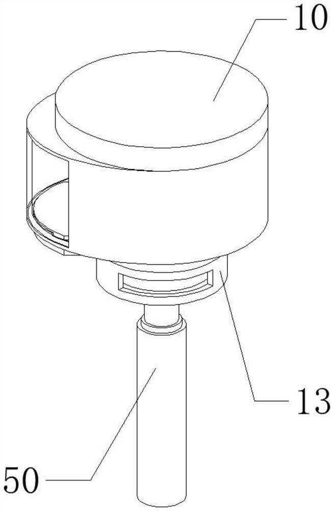
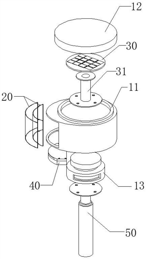
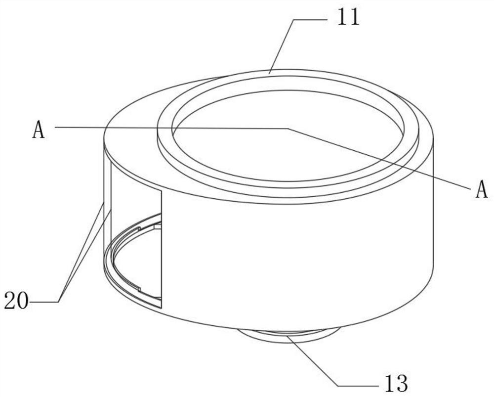
[0052] Embodiment 1: as Figure 1-10 As shown, a windproof retractable antenna structure includes a radome 10 . A hollow channel is provided on the side of the radome 10, and the hollow channel is covered with a double-layer glass part 20 and an air chamber is formed on the cover body of the radome 10; An air duct is arranged on the air duct, and a dew condensation plate 43 is arranged in the air duct, and the dew condensation plate 43 is specifically a metal plate; the radome 10, the double-layer glass part 20, and the dew condensation device 40 form a closed accommodation space; the double-layer glass part 20 is composed of an inner glass 21 and an outer glass 22 from the inside of the radome 10 to the outside; the top of the inner glass 21 is provided with a first gap 211 to form a first passage connecting the air chamber and the accommodation space; The bottom of the layer of glass is provided with a second notch 212, the air channel of the dew condensation device 40 is a...

Embodiment 2

[0057] Embodiment 2: Based on Embodiment 1, the radome 10 includes a housing 11, the top of the housing 11 is provided with an opening, and the housing cover 12 is connected to the opening; the inside of the housing cover 12 is an antenna cavity 121, and the antenna 30 is placed in the antenna cavity 121 Inside.

[0058] The horizontal position of the antenna cavity 121 in the housing cover 12 is higher than the horizontal position of the first channel. When the antenna 30 is placed in the antenna cavity 31 , it can ensure that the antenna as a whole is in a relatively high temperature environment. In addition, adopting such a structure facilitates the daily maintenance and cleaning of the antenna by the user. In order to ensure the tightness between the housing 11 and the housing cover 12 , a sealing gasket can be provided between the housing 11 and the housing cover 12 , since it is a prior art solution, it will not be repeated here.

Embodiment 3

[0059] Embodiment 3: Based on Embodiment 2, a rotating device 13 is connected to the bottom of the housing 11, and a telescopic rod 50 is fixedly connected to the bottom of the rotating device 13; the housing 11 and the telescopic rod 50 can be relatively rotated by the rotating device.

[0060] The rotating device 13 is a manual device, including a rotating part and a base. The kinematic pair formed by the two adopts the rotating pair in the lower pair, and is a sliding friction pair. With this structure, one needs to overcome frictional resistance for rotation, so avoid External force especially sea wind causes improper rotation of the radome, and the second is that the radome and the telescopic rod can be coaxially arranged.


PUM


Abstract

The invention discloses a windproof retractable antenna structure, which comprises a radome. The side of the radome is provided with a hollow channel, which is covered with double-layer glass and forms an air chamber on the cover body of the radome; the bottom of the radome is provided with a condensation device, and the dew condensation device is provided with an air duct. There is a condensation plate in the air duct; the radome, the double-layer glass parts and the condensation device form a closed accommodating space; the double-layer glass parts are composed of inner glass and outer glass from the inside to the outside of the radome; The top of the layer glass is provided with a first gap, forming a first passage connecting the air chamber and the accommodation space; the bottom of the inner layer of glass is provided with a second gap, and the air duct of the dew condensation device is arranged at the second gap, and the second The notch cooperates with the air channel of the dew condensation device to form a second channel connecting the air chamber and the accommodating space. The invention has the technical effect of reducing and delaying the influence of salt spray on the performance of the antenna and improving the service life of the antenna.

Description

technical field [0001] The invention relates to an antenna structure, in particular to a windproof retractable antenna structure. Background technique [0002] When sailing at sea, the air contains a large amount of salt that evaporates with the sea water, which dissolves in small water droplets to form a high concentration of salt spray, and the salt spray will damage electrical components, especially metal components. In addition, in Under the action of sea wind, this effect is particularly obvious on the external electrical components of the ship, so the external components of the ship are usually equipped with windshields. For the sake of daily maintenance and replacement, most of the windshields are detachable parts, which cannot guarantee absolute sealing. In addition, the windshield needs to be opened during daily maintenance, which will cause some salt mist to still enter the inside of the windshield along with the air flow. , affecting the internal metal devices. ...

Claims


Application Information

Patent Timeline
Patent Type & Authority Patents(China)
IPC IPC(8): H01Q1/00H01Q1/10H01Q1/02
CPCH01Q1/005H01Q1/10H01Q1/02
Inventor 崔振东牟春晓杨锐荣王飞迟浩坤
Owner YANTAI UNIV
Learn More