
Pump and liquid conveying equipment

A pump body, liquid technology, applied in mechanical equipment, liquid variable volume machinery, liquid fuel engines, etc., can solve problems such as rapid release and liquid pressure drop

Pending Publication Date: 2021-03-09
HUNAN DIHONG WULIAN TECH CO LTD
View PDF0 Cites 1 Cited by
  • Summary
  • Abstract
  • Description
  • Claims
  • Application Information

AI Technical Summary

Problems solved by technology

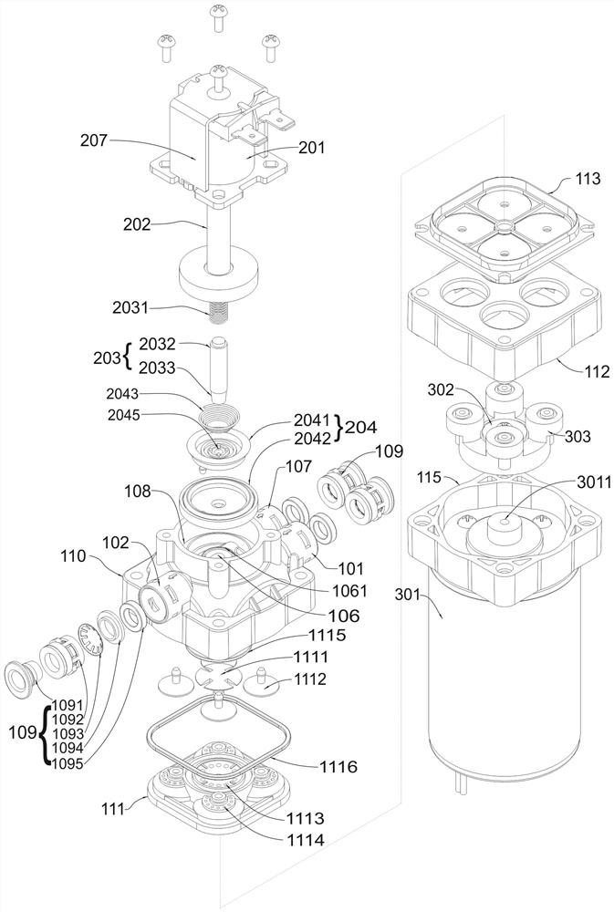
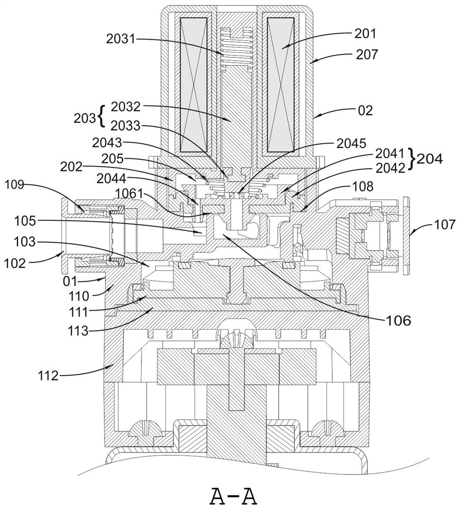
[0004] The embodiment of the present invention provides a pump and liquid conveying equipment, which is used to solve the problem of gradual drop in liquid pressure in a system where the liquid pressure in the pump cannot be quickly released through the output pipeline when the pump is stopped, and realize the liquid pressure in the pump. The purpose of rapid release of liquid pressure; and the removal of air in the liquid inlet pipe and pump as soon as possible to improve the efficiency of liquid absorption

Method used


Image

  • Pump and liquid conveying equipment
  • Pump and liquid conveying equipment
  • Pump and liquid conveying equipment

Examples


Embodiment Construction

[0035] Embodiments of the present invention are described in detail below, examples of which are shown in the drawings, wherein the same or similar reference numerals designate the same or similar elements or elements having the same or similar functions throughout. The embodiments described below by referring to the figures are exemplary only for explaining the present invention and should not be construed as limitations of the present invention.

[0036] In the description of the present invention, it should be understood that the terms "center", "longitudinal", "transverse", "length", "width", "thickness", "upper", "lower", "front" , "Back", "Left", "Right", "Vertical", "Horizontal", "Top", "Bottom", "Inner", "Outer", "Clockwise", "Counterclockwise", etc. The orientation or positional relationship is based on the orientation or positional relationship shown in the drawings, and is only for the convenience of describing the present invention and simplifying the description, ...


PUM


Abstract

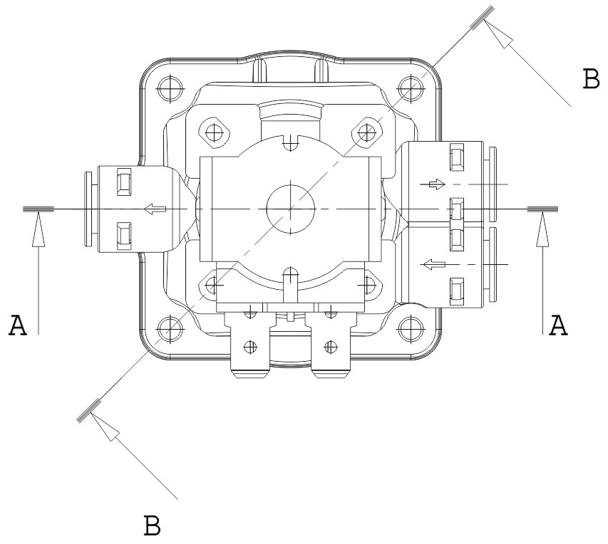
The invention provides a pump and liquid conveying equipment. The pump comprises a pump body which comprises a liquid inlet, a first liquid outlet and a second liquid outlet. The pump body is providedwith a first cavity, a pressurization cavity, a second cavity and a third cavity which sequentially communicate. The pump body is provided with a driving mechanism, and the driving mechanism is usedfor changing the volume size in the pressurization cavity. A control valve body comprises an electromagnetic coil, a sealing shell, a valve element assembly and a valve assembly. The electromagnetic coil is used for generating electromagnetic force to drive the valve element assembly in the sealing shell to act, thus the valve assembly opens or closes a valve opening of the third cavity, and connection between the second cavity and the first cavity is opened or closed. The equipment is used in a system when the pump stops, liquid pressure in the pump cannot be rapidly released through an output end pipeline, the problem that the liquid pressure is reduced gradually is solved, the purpose of releasing the liquid pressure in the pump rapidly is achieved, air in a liquid input pipe and the pump can be exhausted as fast as possible, and the liquid absorbing efficiency is improved.

Description

technical field [0001] The invention relates to the field of liquid conveying machinery and spraying technology, in particular to a pump and liquid conveying equipment. Background technique [0002] When transporting liquid and pressurizing the liquid, a booster pump is usually used. The pump used for fluid boosting is mainly a positive displacement pump, which generates positive and negative pressure by changing the volume in the pump chamber, thereby transporting and boosting the liquid. Such as diaphragm pump, diaphragm pump is a special form of positive displacement pump. It relies on the back and forth agitation of one or more diaphragms to change the volume of the working chamber to transport and pressurize the fluid. In the spray system composed of nozzles , the diaphragm pump pressurizes the liquid and sprays it through the nozzle. When the driving mechanism is composed of a motor, when the motor in the booster pump is powered off, the internal rotor of the motor wil...

Claims


Application Information

Patent Timeline
IPC IPC(8): F04B43/04F04B53/16F04B53/04F04B53/06F04B53/10
CPCF04B43/028F04B43/04F04B53/04F04B53/06F04B53/10F04B53/106F04B53/1087F04B53/162
Inventor 马昆
Owner HUNAN DIHONG WULIAN TECH CO LTD
Learn More