Slide way inclined shaft variable high-pressure plunger pump

A technology of high-pressure plunger pumps and slideways, which is applied in the direction of pumps, multi-cylinder pumps, liquid displacement machinery, etc., can solve the problems of affecting the overall efficiency of the pump, heavy plunger design, rigidity requirement dependence, etc., and achieve the overall structure setting Reasonable, prevent vibration and string movement, improve the effect of wear resistance

Pending Publication Date: 2021-03-09
江苏可奈力机械制造有限公司
View PDF6 Cites 2 Cited by
  • Summary
  • Abstract
  • Description
  • Claims
  • Application Information

AI Technical Summary

Problems solved by technology

[0002] The existing inclined-axis pump (motor) is driven by the cylinder through the plunger to drive the shaft or the shaft through the plunger to drive the cylinder, so the radial force is all borne by the plunger. When the plunger moves in the cylinder hole, the The radial force of the plug in the direction of cylinder movement is relatively large, and it is easy to wear on one side, resulting in cylinder scuffing and easy breakage of the plunger.
Driven by a plunger, it is very dependent on the rigidity of the plunger. The plunger design of all inclined axis pumps will be relatively heavy, which will affect the increase in pump (motor) speed and noise pollution, thereby affecting the overall efficiency of the pump.

Method used


Image

  • Slide way inclined shaft variable high-pressure plunger pump
  • Slide way inclined shaft variable high-pressure plunger pump
  • Slide way inclined shaft variable high-pressure plunger pump

Examples


Embodiment Construction

[0020] The present invention will be further described below in conjunction with the accompanying drawings and embodiments.

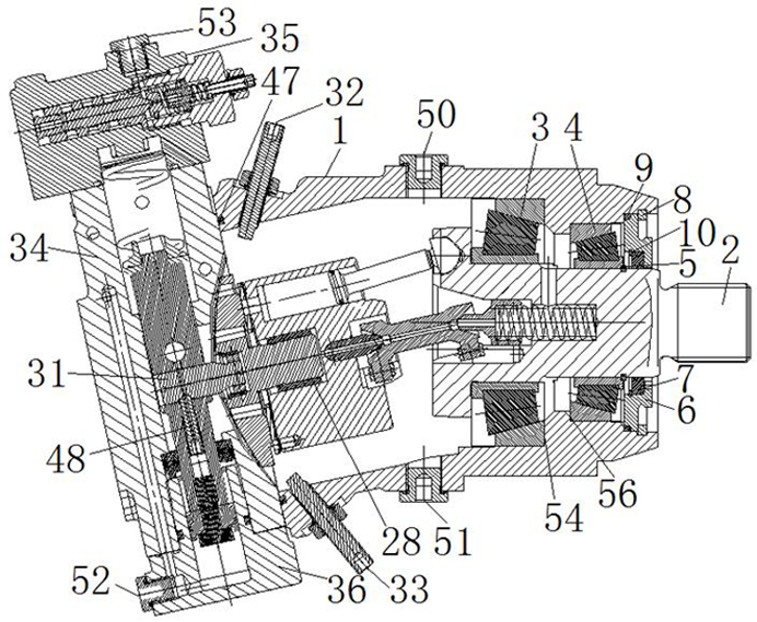
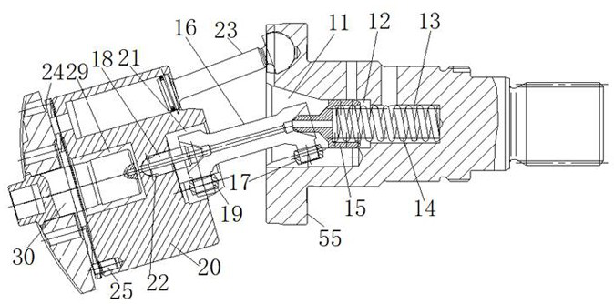
[0021] Such as figure 1 , figure 2 , image 3 , Figure 4 and Figure 5As shown in the present invention, a slideway oblique axis variable high-pressure plunger pump includes a bearing housing 1, a spline shaft 2 is arranged inside the bearing housing 1, and a spline shaft 2 is outside the spline shaft 2. Set two tapered thrust bearings, which are divided into tapered thrust bearing I3 and tapered thrust bearing II4, the outer diameter of the tapered thrust bearing I3 is larger than the outer diameter of the tapered thrust bearing II4, the tapered thrust bearing Fixed in the bearing housing 1, one end of the tapered thrust bearing I3 is placed on the step I54 in the bearing housing 1, and the other end is placed on the step II55 of the spline shaft 2. The tapered thrust bearing II4 One end leans against the step III 56 provided in the bearing hous...


PUM


Abstract

The invention relates to a slide way inclined shaft variable high-pressure plunger pump. The slide way inclined shaft variable high-pressure plunger pump comprises a bearing shell, a spline shaft is arranged in the bearing shell, two conical thrust bearings are arranged outside the spline shaft in a sleeving mode, a connecting hole is formed in the middle of one end of the spline shaft, the connecting hole is divided into a three-fork shaft connecting hole I, an ejector rod connecting hole I and a spring connecting hole from outside to inside, an ejector rod I is arranged in the ejector rod connecting hole I, one end of a spring I extends into a groove of the ejector rod I, a three-fork shaft is arranged in the three-fork shaft connecting hole I, the other end of the three-fork shaft is connected with a cylinder body through an ejector rod II and a ball ring II, a sealing ring plunger is arranged between the cylinder body and the spline shaft, an oil distribution disc is arranged at one end of the cylinder body, a lining plate is arranged at the joint of the cylinder body and the oil distribution disc, the lining plate is connected with the cylinder body through a lining plate positioning pin, and a variable mechanism is connected to one end of the bearing shell. The slide way inclined shaft variable high-pressure plunger pump has the advantages of low noise, light weight, highspeed, high pressure, high efficiency, stable and reliable operation, convenient maintenance and safe use.

Description

technical field [0001] The invention relates to a pump, in particular to a variable variable high pressure plunger pump. Background technique [0002] The existing inclined-axis pump (motor) is driven by the cylinder through the plunger to drive the shaft or the shaft through the plunger to drive the cylinder, so the radial force is all borne by the plunger. When the plunger moves in the cylinder hole, the The radial force of the plug in the direction of the movement of the cylinder body is relatively large, and it is easy to wear on one side, resulting in cylinder scuffing and easy breakage of the plunger. Driven by a plunger, it is very dependent on the rigidity of the plunger. All inclined-axis pump plungers will be designed to be bulky, which will affect the increase in pump (motor) speed and noise pollution, thereby affecting the overall efficiency of the pump. Contents of the invention [0003] Purpose of the invention: The purpose of the invention is to overcome th...

Claims


Application Information

Patent Timeline
IPC IPC(8): F04B1/24F04B1/2014F04B1/2021F04B1/2028F04B1/2042F04B1/324
CPCF04B1/24F04B1/2014F04B1/2021F04B1/2028F04B1/2042F04B1/324
Inventor 孙晓浩王福红汤晓滢梅元国唐雄飞刘峰武建华
Owner 江苏可奈力机械制造有限公司
Why Eureka
Try Eureka