
Wind-assisted hydroelectric generation device and method for wind direction changeable area

A power generation device and auxiliary technology, which is applied in the direction of wind power generation, hydropower generation, wind engine, etc., can solve the problems that the hydropower generation device cannot assist the rotation of the water wheel, and the intermittent work of the wind auxiliary mechanism, so as to reduce intermittent work and avoid damage. Effect

Pending Publication Date: 2021-03-09
汪兴华
View PDF5 Cites 0 Cited by
  • Summary
  • Abstract
  • Description
  • Claims
  • Application Information

AI Technical Summary

Problems solved by technology

[0003] The purpose of the present invention is to provide a wind-assisted hydroelectric power generation device and method used in areas with variable wind directions, so as to solve the problem of using the wind-assisted hydroelectric power generation device in areas with dry and variable wind directions proposed in the background art. It will cause the wind auxiliary mechanism to work intermittently, resulting in the problem that the hydroelectric power generation device still cannot assist the rotation of the water wheel

Method used


Image

  • Wind-assisted hydroelectric generation device and method for wind direction changeable area
  • Wind-assisted hydroelectric generation device and method for wind direction changeable area
  • Wind-assisted hydroelectric generation device and method for wind direction changeable area

Examples


Embodiment Construction

[0024] The following will clearly and completely describe the technical solutions in the embodiments of the present invention with reference to the accompanying drawings in the embodiments of the present invention. Obviously, the described embodiments are only some, not all, embodiments of the present invention. Based on the embodiments of the present invention, all other embodiments obtained by persons of ordinary skill in the art without making creative efforts belong to the protection scope of the present invention.

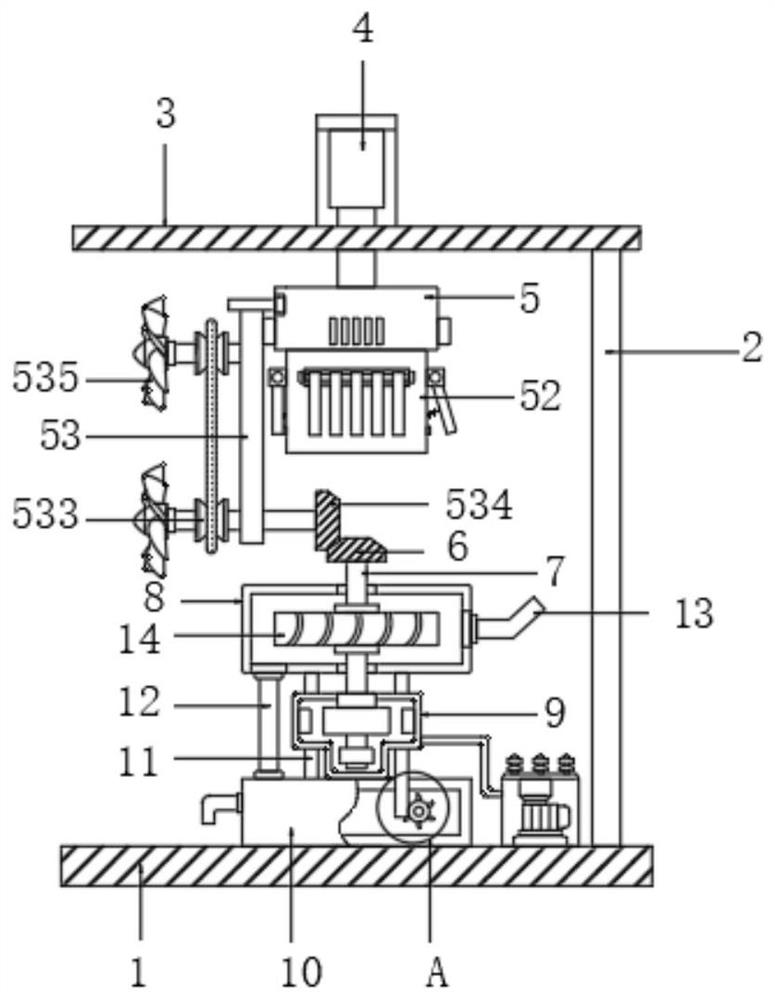
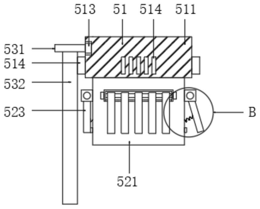
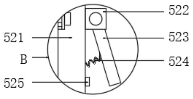
[0025] The present invention provides a technical solution: a wind-assisted hydroelectric power generation device used in areas with variable wind direction, please refer to figure 1 , including a bottom plate 1, a support frame 2 is fixedly connected to the top right side of the bottom plate 1, a top plate 3 is connected to the top of the support frame 2, a mounting frame is arranged on the top of the top plate 3, and a hydraulic cylinder 4 is arranged on the ...


PUM


Abstract

The invention discloses a wind-assisted hydroelectric generation device and method for a wind direction changeable area, and belongs to the technical field of hydroelectric generation. The wind-assisted hydroelectric generation device comprises a bottom plate, wherein a supporting frame is fixedly connected to the right side of the top of the bottom plate, a top plate is connected to the top of the supporting frame, a mounting frame is arranged at the top of the top plate, a hydraulic cylinder is arranged on the mounting frame, a piston rod at the bottom of the hydraulic cylinder penetrates through the top plate to be connected with a wind driving mechanism, the bottom of the wind driving mechanism is connected with a driven bevel gear, the driven bevel gear sleeves a water wheel shaft, the bottom end of the water wheel shaft penetrates through a water inlet tank to be connected with a generator, a water drainage tank is connected to the bottom of the generator, and the bottom end of the water drainage tank is fixedly connected to the bottom plate. It is ensured that fan blades can always face a wind receiving side, thus, the circumstance that the wind-assisted mechanism works intermittently can be greatly reduced, and the wind-assisted hydroelectric generation in the wind direction changeable area has continuity.

Description

technical field [0001] The invention relates to the technical field of hydropower generation, in particular to a wind-assisted hydropower generation device and method for areas with variable wind directions. Background technique [0002] Hydropower generation is a way of generating electricity. The water energy used is mainly the potential energy stored in the water body. When the water flows through the water turbine, the water turbine is driven by the water flow to rotate, and the water turbine drives the generator to generate electricity. The mechanical energy is converted into electrical energy, and then through the transformer Electricity and power transmission and distribution equipment send electricity to users. In some arid areas, the water flow in the area is small due to drought, resulting in unsatisfactory rotation of the water wheel. Therefore, it is necessary to use wind auxiliary mechanisms to assist the rotation of the water wheel, but When the wind-assisted h...

Claims


Application Information

Patent Timeline
IPC IPC(8): F03B13/00F03B11/00F03D7/02F03D9/00F03D15/00F03D80/00
CPCF03B11/00F03B13/00F03D7/0204F03D9/008F03D15/00F03D80/00Y02E10/20Y02E10/72
Inventor 汪兴华
Owner 汪兴华
Learn More