
Building outer wall supporting device and using method thereof

A technology for supporting devices and building exterior walls, which is applied in the processing of building materials, construction, building construction, etc., can solve the problems of inability to adjust the angle of support, poor support effect, waste of materials and labor, etc., to avoid device defects, Improve the support effect and improve the effect of the application range

Inactive Publication Date: 2021-03-09
陈丽青
View PDF0 Cites 0 Cited by
  • Summary
  • Abstract
  • Description
  • Claims
  • Application Information

AI Technical Summary

Problems solved by technology

[0004] The purpose of the present invention is to provide a support device for building exterior walls and its use method, in order to solve the problem that the general support devices proposed in the above background technology often use a large amount of auxiliary materials, which not only consumes materials and labor, but also has many potential safety hazards. To adapt to the current building construction, at the same time, the traditional support can only support one point of the outer wall, the support effect is poor, and multiple sets of support devices are required to work at the same time, which increases the cost investment, and the general support device cannot adjust the angle of the support. Changing the support direction reduces the application range of the device and brings about the problem of device defects

Method used


Image

  • Building outer wall supporting device and using method thereof
  • Building outer wall supporting device and using method thereof
  • Building outer wall supporting device and using method thereof

Examples


Embodiment Construction

[0030] The technical solutions in the embodiments of the present invention will be clearly and completely described below in conjunction with the embodiments of the present invention. Apparently, the described embodiments are only some of the embodiments of the present invention, not all of them. Based on the embodiments of the present invention, all other embodiments obtained by persons of ordinary skill in the art without creative efforts fall within the protection scope of the present invention.

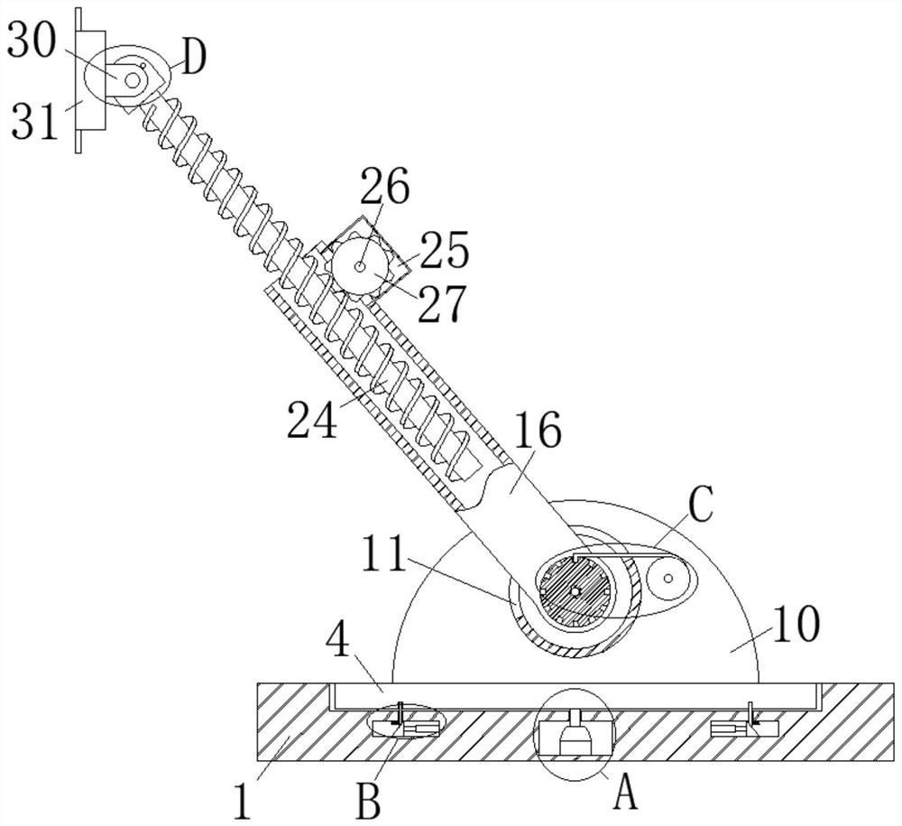
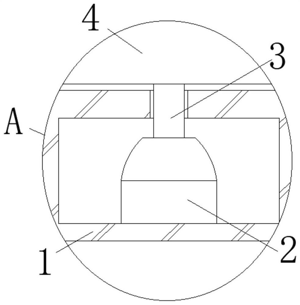
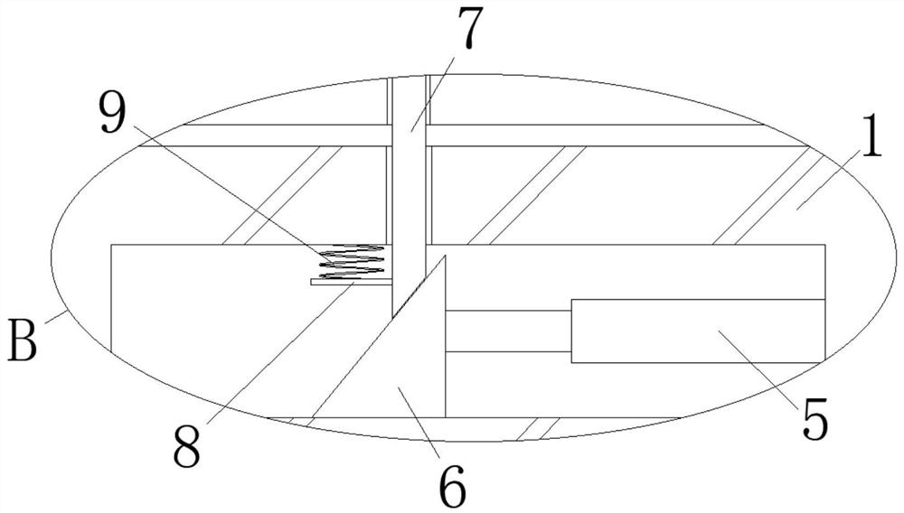
[0031] like Figure 1-10As shown, a support device for building exterior walls includes a base 1, and a cavity 1, a cavity 2 and a groove 1 are provided in the base 1, a motor 2 is installed on the bottom surface of the cavity 1, and the output end of the motor 2 is fixed. A transmission shaft 3 is connected, and the other end of the transmission shaft 3 extends into the groove 1, and a turntable 4 is fixedly connected to the extension end of the transmission shaft 1 3, and the tu...


PUM


Abstract

The invention discloses a building outer wall supporting device and a using method thereof. The supporting device comprises a base, a first cavity, a second cavity and a first groove are formed in thebase, a motor is installed on the bottom face of the first cavity, a first transmission shaft is fixedly connected to the output end of the motor, and the other end of the first transmission shaft extends into the first groove. The extending end of the first transmission shaft is fixedly connected with a rotary table, the rotary table is rotatably connected with the first groove in a sleeving mode, an electric push rod is installed on the side wall of the second cavity, the other end of the electric push rod is fixedly connected with a first sliding block, the first sliding block is slidablyconnected with the bottom face of the second cavity, and the side wall of the first sliding block is slidably connected with a first clamping rod. The top end of the first clamping rod extends into the first groove. The supporting angle can be adjusted, meanwhile, the supporting direction can be changed, the application range of the device is widened, device defects are avoided, supporting pointscan be increased, the supporting effect is improved, multiple sets of supporting devices do not need to act at the same time, and cost input is reduced.

Description

technical field [0001] The invention belongs to the field of construction equipment, in particular to a support device for building exterior walls and a method for using the same. Background technique [0002] In construction engineering, due to the influence of objective conditions, it is easy to cause some reinforced concrete horizontal components to be unable to be completely penetrated, and the components cannot bear the load of the structure during the construction process and before the components are completely penetrated, so that the outer wall of the building is easy to fall, so A bracing device is required to maintain the stability of the outer wall. [0003] The general support devices on the market use a lot of auxiliary materials, which not only consumes materials and labor, but also has many safety hazards, which cannot adapt to the current building construction. At the same time, the traditional support can only support one point of the outer wall, and the sup...

Claims


Application Information

Patent Timeline
Patent Type & Authority Applications(China)
IPC IPC(8): E04G21/26
CPCE04G21/26
Inventor 陈丽青
Owner 陈丽青
Learn More