
Device and method for achieving adjustment of stress or position between two parts through inclined wedges

A technology of oblique wedges and parts, applied in the direction of lifting devices, fixing devices, hoisting devices, etc., can solve the problems of high cost, troublesome disassembly, and complexity, and achieve the effect of simple structure, low cost, and easy implementation

Pending Publication Date: 2021-03-09
CHINA NAT HEAVY MACHINERY RES INSTCO
View PDF10 Cites 0 Cited by
  • Summary
  • Abstract
  • Description
  • Claims
  • Application Information

AI Technical Summary

Problems solved by technology

[0003] Using the above method to adjust the stress state or position between the two parts is relatively complicated, relatively large, and the cost is high and disassembly is troublesome.

Method used


Image

  • Device and method for achieving adjustment of stress or position between two parts through inclined wedges
  • Device and method for achieving adjustment of stress or position between two parts through inclined wedges
  • Device and method for achieving adjustment of stress or position between two parts through inclined wedges

Examples


Embodiment 1

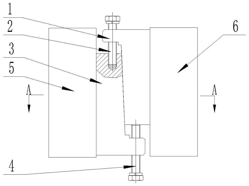
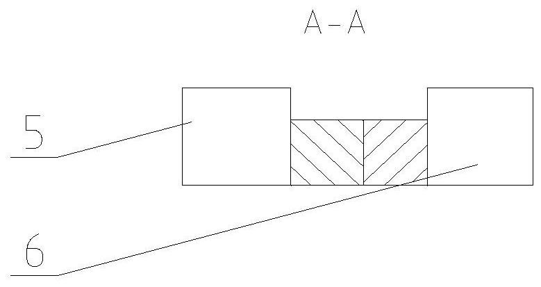
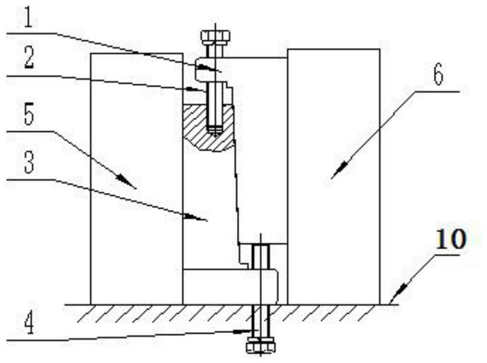
[0035] refer to Figure 1 to Figure 7 The shown device that utilizes a wedge to realize force or position adjustment between two components includes a first wedge 1, a second wedge 3, a first component 5, a second component 6, a fixing member, an adjusting member and a fixing seat 10 The first part 5 and the second part 6 are placed on the fixed seat 10; the first wedge 1 and the second wedge 3 are oppositely arranged between the first part 5 and the second part 6, And the first wedge 1 and the second wedge 3 are in contact with the first component 5 and the second component 6 or the second wedge 3 is fixedly connected with the first component 5, and the first wedge 1 is in contact with the second component 6; The fixing piece passes through one end of the first wedge 1 and is detachably fixed to one end of the second wedge 3 , and the adjusting piece passes through the other end of the second wedge 3 and abuts against the end of the first wedge 1 another side.

[0036] In a...

Embodiment 2

[0041] refer to figure 1 and image 3 The shown device using a wedge to realize force or position adjustment between two components differs from Embodiment 1 in that the first bolt 2 is used as the fixing member.

[0042] Preferably, the second bolt 4 is used for the adjustment member.

[0043] In actual use, the fixing part and the adjusting part adopt this technical solution, and only need to screw the first bolt 2 and the second bolt 4 to achieve the purpose of adjustment or locking, which is not only simple and convenient to operate, but also low in cost.

Embodiment 3

[0045] refer to figure 1 , image 3 , Figure 4 and Figure 5 The shown device using a wedge to realize force or position adjustment between two parts is based on Embodiment 1 or Embodiment 3: the first wedge 1 is an integrated structure composed of upper and lower parts; the first The upper part of the wedge 1 is a rectangular plate-like structure and one end is opened with a first through hole 8 for connecting the fixing member through the plate surface; the lower part of the first wedge 1 is a columnar body and one of the surfaces is a slope, and the other surfaces It is a plane; the contact side of the plate-shaped structure with the second component 6 is flush with the opposite side of the inclined surface on the columnar body.

[0046] Further, the width of the connecting end of the columnar body and the rectangular plate-like structure is greater than the width of the other end and smaller than the width of the rectangular plate-like structure.

[0047] In actual us...


PUM


Abstract

The invention belongs to the technical field of metallurgical equipment, and particularly relates to a device and method for achieving adjustment of the stress or the position between two parts through inclined wedges. The device comprises the first inclined wedge, the second inclined wedge, the first part, the second part, a fixing piece, an adjusting piece and a fixing base. The first part and the second part are arranged on the fixing base. The first inclined wedge and the second inclined wedge are oppositely arranged between the first part and the second part, and both the first inclined wedge and the second inclined wedge make contact with the first part and the second part, or the second inclined wedge is fixedly connected with the first part, and the first inclined wedge makes contact with the second part. The fixing piece penetrates through one end of the first inclined wedge and is detachably fixed to one end of the second inclined wedge, and the adjusting piece penetrates through the other end of the second inclined wedge and abuts against the other end of the first inclined wedge. The adjusting piece is adjusted, the fixing piece is fastened, the paired cooperation of the first inclined wedge and the second inclined wedge is utilized, and therefore the adjustment of the stress or the position between the first part and the second part is achieved. The device and method are simple in structure, easy to implement and low in cost.

Description

technical field [0001] The invention belongs to the technical field of metallurgical equipment, and in particular relates to a device and a method for realizing stress or position adjustment between two parts by using a wedge. Background technique [0002] In the field of metallurgy, in order to change the local force state of two components with a large force and a certain distance in the equipment or the two legs of a component, preloading devices are often used to adjust the force state; in order to change The relative position between the two components often uses a lifting device to adjust the lifting of the components to achieve the adjustment of the relative position between the two components. [0003] Using the above method to adjust the stress state or position between the two parts is relatively complicated, large-scale, costly and troublesome to disassemble. Contents of the invention [0004] The invention provides a device and method for adjusting the force o...

Claims


Application Information

Patent Timeline
Patent Type & Authority Applications(China)
IPC IPC(8): B66F19/00F16B1/04
CPCB66F19/00F16B1/04
Inventor 常瑜汪恩辉何潜左雁冰丛阳阳
Owner CHINA NAT HEAVY MACHINERY RES INSTCO
Learn More