Eureka AIR delivers breakthrough ideas for toughest innovation challenges, trusted by R&D personnel around the world.

Production equipment and method for a puncture needle ultrasound region

A technology for production equipment and puncture needles, which is applied in the production equipment and manufacturing fields of the ultrasound area of ​​puncture needles, and can solve problems such as inability to ensure operators, injuries, and patient injuries

Active Publication Date: 2022-04-26
广东百越医疗器械有限公司
View PDF0 Cites 1 Cited by
  • Summary
  • Abstract
  • Description
  • Claims
  • Application Information

AI Technical Summary

Problems solved by technology

[0002] In recent years, with the help of the widespread use of Doppler ultrasound in clinical practice, its visualization features have brought more intuitive judgments to clinical diagnosis and treatment. Ultrasound is no longer the exclusive weapon of the ultrasound department. Conduct non-invasive ultrasonic exploration at targeted locations, and carry out low-injury and high-precision punctures, insert different types of puncture needles or treatment needles into designated locations, perform injections, samples, or place catheters, etc. For example, the anesthesiology department conducts ultrasound-guided nerve Block technology, interventional puncture technology under ultrasound in interventional department, ozone puncture therapy technology under ultrasound guidance in pain department, radio frequency therapy technology; ultrasound-guided biopsy puncture technology in internal medicine department, and ultrasound-guided central venous puncture Technology, etc., all require the cooperation of ultrasound and puncture needle to achieve the purpose of diagnosis and treatment, and the echo intensity of the puncture needle in the ultrasonic beam directly determines whether the operator can observe the real-time position of the puncture needle, but different types of ultrasound-guided puncture are very important The length, diameter, puncture depth, and puncture angle of the puncture needles are all different, so it is impossible to ensure that the operator can effectively receive a strong enough echo when using ultrasound-guided puncture; if the puncture needle cannot be accurately observed, especially the needle tip If the position is too small, it is very likely that the puncture will cause damage to non-target parts such as blood vessels, nerves, tissues, and organs. In severe cases, it may cause irreparable damage to the patient.

Method used


Image

  • Production equipment and method for a puncture needle ultrasound region
  • Production equipment and method for a puncture needle ultrasound region
  • Production equipment and method for a puncture needle ultrasound region

Examples


Embodiment 1

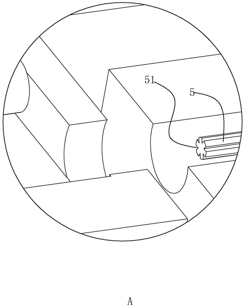
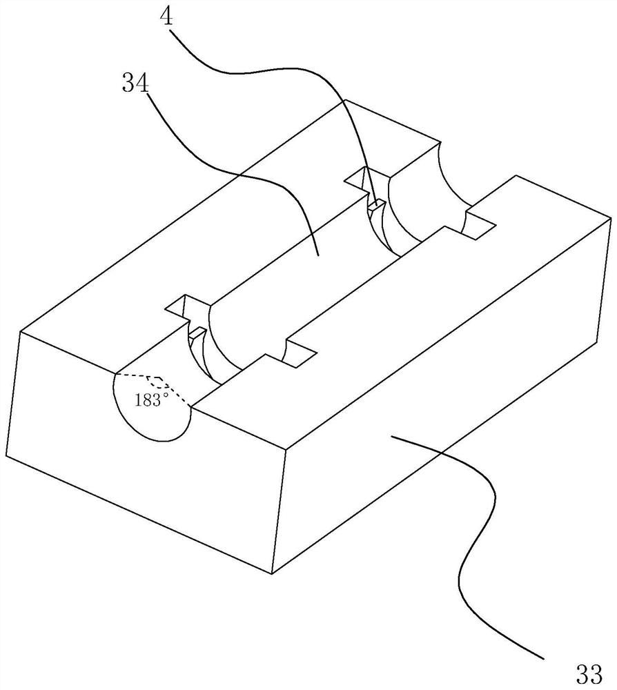
[0060] Example 1, such as Figure 1-Figure 4 As shown, a production equipment for a puncture needle ultrasound area includes a base 1, the base 1 is provided with two slide rails, the slide table 21 slides back and forth along the slide rails, and a screw assembly, and the screw assembly is driven by a servo motor, so the distance and frequency of sliding back and forth of the slide table 21 can be controlled by controlling the servo motor.

[0061] One side of the slide table 21 is provided with a jaw 22, which is a chuck; the jaw 22 can be automatically opened and closed by PLC control; the jaw 22 is connected to the motor shaft of the first motor 23, and the first motor 23 is a servo motor. The forward and reverse rotation of the clamp mouth 22 can be controlled by controlling the forward and reverse rotation of the first motor 23 .

[0062] Therefore, through the cooperation of the slide table 21 and the first motor 23, the forward and reverse rotation and the back and fo...

Embodiment 2

[0075] Embodiment 2, a manufacturing method of a puncture needle.

[0076] (1) Prepare the needle core of the puncture needle:

[0077] Take the stainless steel billet, cut it into a rod, then heat the rod, stretch it step by step through the drawing die, cool it, and then cut it to form a needle core column of the required length and diameter;

[0078] Using a cutting grinder to cut the head of the needle core column to form a needle point with a piercing edge surface, and then obtain a rough needle core product with a needle point;

[0079] placing the obtained needle core crude product in an abrasive suspension, and using ultrasonic waves to vibrate the abrasive suspension to polish the needle core to obtain a polished needle core;

[0080] (2) Prepare the needle tube of the puncture needle:

[0081] Take a stainless steel billet, subject it to hot extrusion treatment at a temperature of 260°C to form a stainless steel thick plate, and then water quench the stainless stee...


PUM


Abstract

The invention discloses a production equipment and a manufacturing method of a puncture needle ultrasonic area. The key point of the technical scheme is that the production equipment of the puncture needle ultrasonic area includes a base, and the base slides with a sliding table that moves back and forth. The sliding table is equipped with The jaw that clamps the puncture needle and the first motor that drives the jaw to rotate forward and backward; the base is provided with a lower mold, the outlet of the jaw is provided with a lower mold, and the lower mold is provided with a positioning groove for the insertion and rotation of the puncture needle. The positioning groove is aligned with the mouth of the clip; the base is provided with an upper die, the upper die includes a tapered punch, and the sharp end of the punch points to the notch of the positioning groove; the manufacturing method of the puncture needle is to place the needle tube along the positioning The end of the groove slides into the positioning groove, and through the guidance of the calibration needle in the positioning groove, the inner end of the needle tube slides into the clamp to fix; starting from the outer end of the needle tube, it is pressed down by a punch with a buffer block, The tapered punch is used to form a multi-reflective ultrasonic area, which actively enhances the ultrasonic echo and reduces the risk of puncture.

Description

technical field [0001] The invention relates to a production device and a manufacturing method of a puncture needle ultrasonic region. Background technique [0002] In recent years, with the help of the widespread use of Doppler ultrasound in clinical practice, its visualization features have brought more intuitive judgments to clinical diagnosis and treatment. Ultrasound is no longer the exclusive weapon of the ultrasound department. Conduct non-invasive ultrasonic exploration at targeted locations, and carry out low-injury and high-precision punctures, insert different types of puncture needles or treatment needles into designated locations, perform injections, samples, or place catheters, etc. For example, the anesthesiology department conducts ultrasound-guided nerve Block technology, interventional puncture technology under ultrasound in interventional department, ozone puncture therapy technology under ultrasound guidance in pain department, radio frequency therapy tec...

Claims


Application Information

Patent Timeline
Patent Type & Authority Patents(China)
IPC IPC(8): B29C45/14A61B17/34
CPCB29C45/14008B29C45/1418A61B17/34A61B2017/3413B29C2045/14237
Inventor 王永王垦颜学清温俊滔
Owner 广东百越医疗器械有限公司
Why Eureka
Eureka Blog
Learn More