Glass container water-milling edge polishing device capable of automatically feeding
A glass container, automatic feeding technology, applied in grinding drive device, grinding/polishing equipment, grinding machine and other directions, can solve the problems of low work efficiency, cumbersome operation process, labor-intensive, etc., to improve work efficiency, simple operation, Manpower saving effect
- Summary
- Abstract
- Description
- Claims
- Application Information
AI Technical Summary
Problems solved by technology
Method used
Image
Examples
Embodiment 1
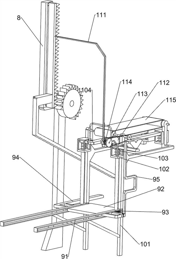
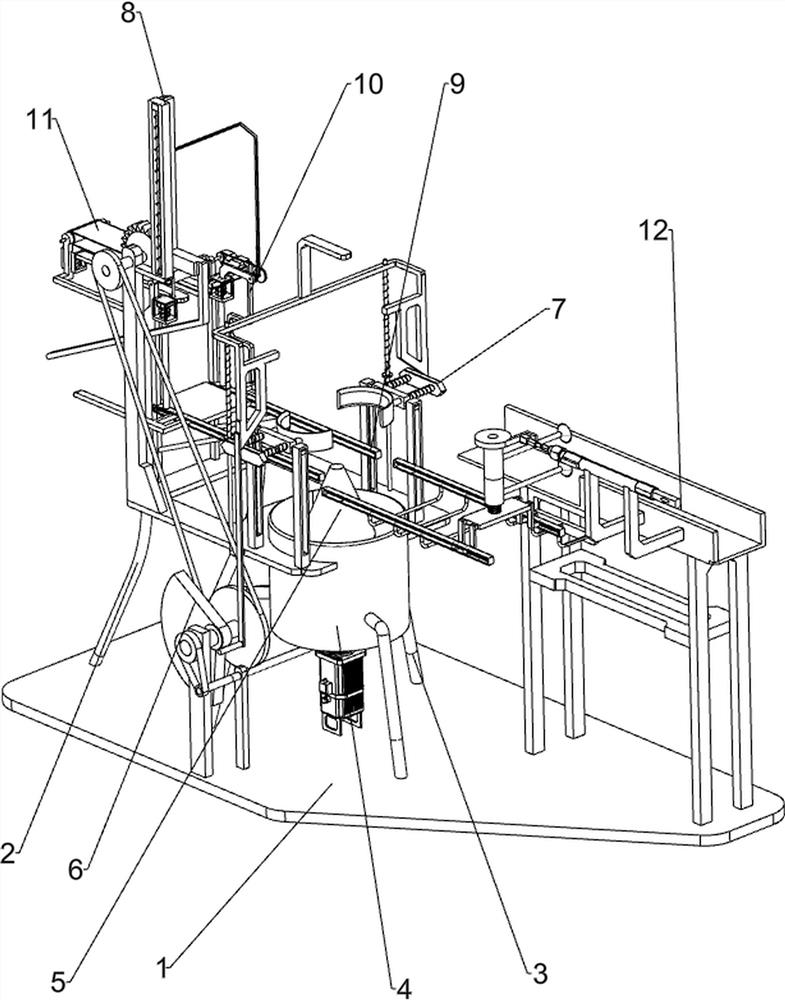
[0027] A glass container water grinding and edge polishing device that can automatically feed materials, such as Figure 1 to Figure 4 As shown, it includes a base plate 1, a first support frame 2, a first support rod 3, a fixed barrel 4, a first rotating shaft 41 and a tapered grinding block 5. The rear side of the top of the base plate 1 is connected with the first support frame 2. The middle of the top is connected with three first support rods 3 evenly spaced along the circumferential direction, the fixed barrel 4 is connected between the three first support rods 3, the fixed barrel 4 is connected with the first support frame 2, and the fixed barrel 4 is connected with the first A rotating shaft 41, the upper part of the first rotating shaft 41 is connected with a tapered grinding block 5, and also includes a rotating mechanism 6, a clamping mechanism 7, a moving mechanism 8, a feeding mechanism 9 and a pressing mechanism 10, the bottom plate 1 and the first supporting fram...
Embodiment 2
[0035] On the basis of Example 1, such as Figure 4 As shown, a transmission mechanism 11 is also included, and the transmission mechanism 11 includes a second rack 111, a third support rod 112, a fifth rotating shaft 113, a one-way tooth 114 and a belt drive assembly 115, and the first rack 86 is connected with The second rack 111, one of the fourth slide rails 102 is connected with a third support rod 112, the third support rod 112 is rotatably connected with a fifth rotating shaft 113, and the fifth rotating shaft 113 is connected with a one-way tooth 114. The two racks 111 mesh with the one-way teeth 114 , and the belt drive assembly 115 is rotatably connected between the upper parts of the second support frame 101 on both sides, and the one-way gear 114 is in transmission connection with one of the transmission shafts of the belt drive assembly 115 .
[0036] When placing the glass container, the glass container can be evenly spaced between the two supporting plates 104, ...
Embodiment 3
[0038] On the basis of Example 2, such as Figure 5 As shown, it also includes a material suction mechanism 12, and the material suction mechanism 12 includes a fourth support frame 121, a discharge rail 122, a cylinder 123, a second push plate 124, a fifth slide rail 125, a sixth spring 126, a slide bar 127, slide plate 128, sixth rotating shaft 129, turntable 1210, second connecting rod 1211, torsion spring 1212, rotating rod 1213 and suction cup 1214, bottom plate 1 top right front side is connected with fourth support frame 121, and the top of fourth support frame 121 is connected There is a discharge rail 122, a cylinder 123 is installed on the discharge rail 122, a second push plate 124 is connected to the telescopic rod of the cylinder 123, two fifth slide rails 125 are connected to the left side of the discharge rail 122, and two fifth slide rails 125 are connected to the left side of the discharge rail 122. Slide rails 125 are slideably connected with slide bars 127, ...
PUM
 Abstract
Description
Claims
Application Information
 - R&D
- Intellectual Property
- Life Sciences
- Materials
- Tech Scout
- Unparalleled Data Quality
- Higher Quality Content
- 60% Fewer Hallucinations
Browse by: Latest US Patents, China's latest patents, Technical Efficacy Thesaurus, Application Domain, Technology Topic, Popular Technical Reports.
© 2025 PatSnap. All rights reserved.Legal|Privacy policy|Modern Slavery Act Transparency Statement|Sitemap|About US| Contact US: help@patsnap.com


