
Spraying device for producing and processing fan blades

A technology of spraying device and fan blade, which is applied to spraying device, cleaning method using tools, device for coating liquid on the surface, etc. The effect of efficiency

Inactive Publication Date: 2021-03-09
安徽朗迪叶轮机械有限公司
View PDF9 Cites 8 Cited by
  • Summary
  • Abstract
  • Description
  • Claims
  • Application Information

AI Technical Summary

Problems solved by technology

[0004] However, the existing spraying device is inconvenient to complete the double-sided cleaning, double-sided spraying, double-sided drying, conveying and other processing processes for the fan blades at one time without interruption, so as to improve the efficiency of the fan blade processing process; and it is not convenient to adhere to the outer wall of the blades. dust removal and collection

Method used


Image

  • Spraying device for producing and processing fan blades
  • Spraying device for producing and processing fan blades
  • Spraying device for producing and processing fan blades

Examples


Embodiment 1

[0032] A spraying device for the production and processing of fan blades, including a box body 1, a first cavity 2 and a second cavity 3 are arranged inside the box body 1, and a feed plate 21 is fixedly installed in the middle of the upper end of the box body 1 , the lower middle position of the feed plate 21 is provided with two rotating shafts 17 running through the front and rear ends of the box body 1, and the two rotating shafts 17 are located in the two rotating shafts 17 inside the first cavity 2, and the outer walls of the two rotating shafts 17 are uniform. Rollers 18 are fixedly installed, and the outer walls of the two rollers 18 are fixedly equipped with a plurality of bristles, and the outer walls of the two rotating shafts 17 are fixedly equipped with pulleys 20 near the front ends, and the two pulleys 20 are crossed. Belt, the front end of one of the two pulleys 20 is fixedly equipped with a second motor 19, and the second motor 19 is fixedly connected to the fr...

Embodiment 2

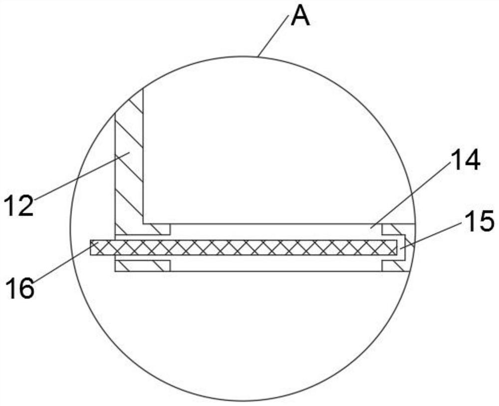
[0034] One side of the first cavity 2 is provided with a third opening opened on the side wall of the box body 1. The side of the third opening is provided with a mounting frame 12 fixedly connected to the side wall of the box body 1, and one side of the mounting frame 12 is fixedly installed. There is a first support plate, and the lower end of the first support plate is fixedly installed with a first motor 13, and one side of the first motor 13 is fixedly installed with a movable rod that runs through the installation frame 12, and the outer wall of the movable rod is fixedly installed with two fans. Leaves, the lower end inner wall of the installation frame 12 is provided with a through groove 14, and the lower end side wall of the installation frame 12 is provided with an installation groove 15, the installation groove 15 communicates with the through groove 14, and the inside of the installation groove 15 is equipped with a dust filter plate 16.

Embodiment 3

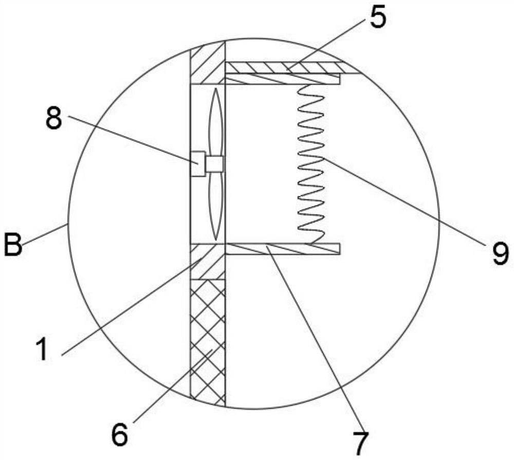
[0036] A first opening is provided between the first cavity 2 and the second cavity 3, and two spray guns 4 penetrating through the side walls of the box body 1 are provided below the first opening, and two spray guns 4 are provided below the two spray guns 4 with The baffles 5 fixedly connected to the side walls at the front and rear ends of the box body 1;

[0037] The bottom of the baffle plate 5 is provided with two drying assemblies, the drying assembly includes a fan body 8 fixedly installed on the side wall of the box body 1, and one side of the fan body 8 is provided with a heating wire 9, and the upper and lower ends of the heating wire 9 are fixed. A horizontal plate 7 is installed, and both horizontal plates 7 are fixedly connected with the side wall of the box body 1;

[0038] Two groups of drying components are arranged on both sides of the box body 1 respectively. The two groups of drying components are arranged in opposite directions. The two groups of drying co...


PUM


Abstract

The invention discloses a spraying device for producing and processing fan blades in the technical field of fan blade processing and spraying. The spraying device comprises a box body, a first cavityand a second cavity are formed in the box body, a feeding plate is fixedly mounted in the middle of the upper end of the box body, two rotating shafts penetrating through the front end and the rear end of the box body are arranged in the middle of the lower portion of the feeding plate, the two rotating shafts are both located in the first cavity, and rollers are fixedly installed on the outer walls of the two rotating shafts. By means of the spraying device for producing and processing the fan blades, the fan blades can be continuously subjected to double-sided cleaning, double-sided spraying, double-sided drying, conveying and other machining procedures at a time, and thus the efficiency of the fan blade machining procedures is improved; dust attached to the outer walls of the blades isprevented from affecting the spraying effect of the blades, and the blade spraying effect is improved; and a dust filtering plate can be pulled out of a mounting groove to be cleaned or replaced, meanwhile, dust on the dust filtering plate can be moved to the outside, and the using effect is good.

Description

technical field [0001] The invention relates to the technical field of fan blade processing and spraying, in particular to a spraying device for fan blade production and processing. Background technique [0002] Spraying machine is a special coating equipment that adopts spraying technology. It pressurizes the inhaled paint, and transports the paint to the spray gun of the spraying machine through a high-pressure hose. The spray gun instantly atomizes the paint and releases it to the surface of the object to be coated. The spraying machine is mainly composed of a feeding device, a spray gun, and an atomization source. Suitable for leather handbags, gift packaging, furniture, footwear, automobile manufacturing and other industries. [0003] The fan is a machine that relies on the input mechanical energy to increase the gas pressure and discharge the gas. It is a driven fluid machine. Fan is China's customary abbreviation for gas compression and gas conveying machinery. Usua...

Claims


Application Information

Patent Timeline
Patent Type & Authority Applications(China)
IPC IPC(8): B05B16/20B05B13/02B05D3/00B05D3/04B08B1/02B08B15/04B08B1/20
CPCB05B16/20B05B13/0278B05B13/0221B05D3/0413B05D3/002B08B15/04B08B1/20
Inventor 潘可车增贤卜彦雄
Owner 安徽朗迪叶轮机械有限公司
Learn More