
Device for testing performance of valve

A technology for testing valves and performance, applied in measuring devices, mechanical valve testing, instruments, etc., can solve the problems of low test efficiency, large measurement error, poor detection accuracy of pneumatic valves, etc., and achieve the effect of improving test efficiency and saving manpower

Pending Publication Date: 2021-03-05
LANGFANG KIM YUN ELECTRIC CO LTD +1
View PDF0 Cites 0 Cited by
  • Summary
  • Abstract
  • Description
  • Claims
  • Application Information

AI Technical Summary

Problems solved by technology

[0006] 1. The operation of manually blocking or connecting the air port of the pneumatic valve is slow, which makes the test efficiency low
[0007] 2. It is laborious to manually drive the handle
[0008] 3. The measurement error of the rotation angle of the handle is relatively large, resulting in poor detection accuracy for the starting angle of the pneumatic valve opening

Method used


Image

  • Device for testing performance of valve
  • Device for testing performance of valve
  • Device for testing performance of valve

Examples


Embodiment Construction

[0053] In order to enable those skilled in the art to better understand the technical solutions of the present invention, the present invention will be described in detail below in conjunction with the accompanying drawings and specific embodiments.

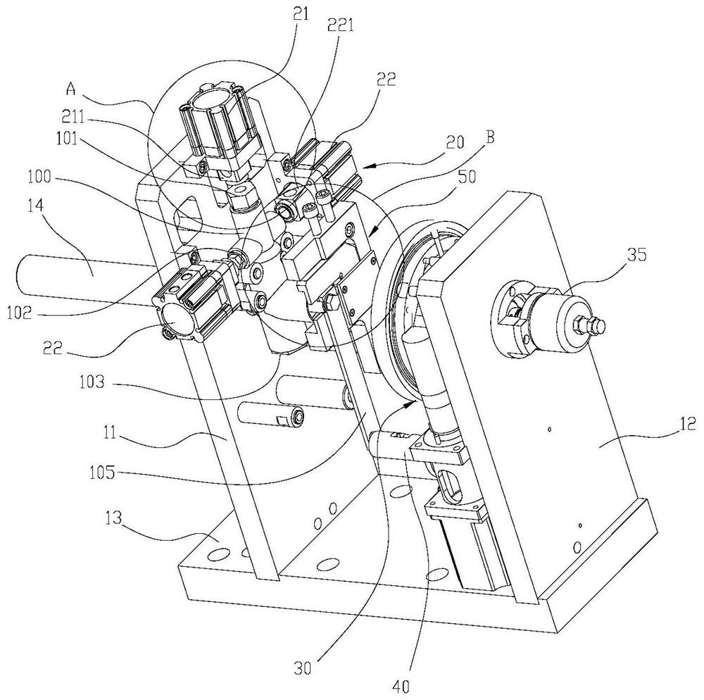
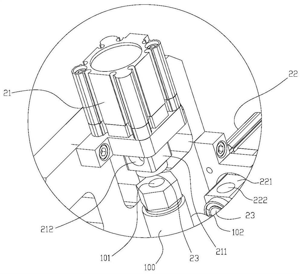
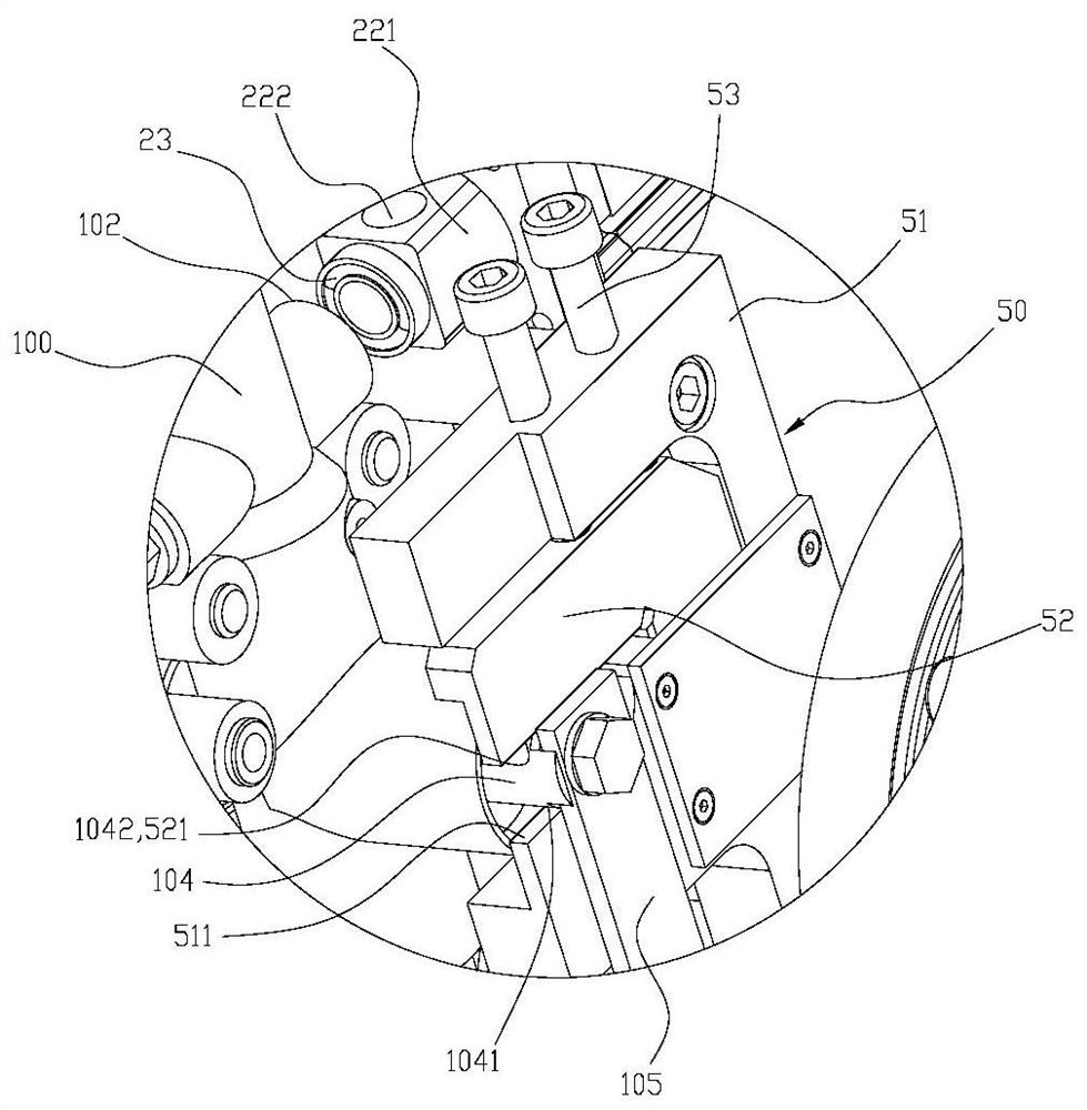
[0054] Such as figure 1As shown, the embodiment of the present invention discloses a device for testing the performance of a valve, the valve is specifically a pneumatic valve 100, the pneumatic valve 100 has an inlet 101, two outlets 102 and an outlet 103 , the air inlet 101 is set opposite to the exhaust port 103, and the two air outlets 102 are set opposite to each other. The pneumatic valve 100 has a handle rod 105, which is connected to one end of the valve core 104 protruding from the valve body. Specifically, the protruding end of the valve core 104 is formed with two tables 1041, 1042, and the handle rod 105 is provided with The hole matched with the protruding end enables the rotation of the handle rod 105 to drive the ...


PUM


Abstract

The invention discloses a device for testing the performance of a valve. The device for testing the performance of the valve comprises a first holding body, an air cylinder group, a second holding body and a driving mechanism, wherein the valve is detachably arranged on the first holding body; the air cylinder group at least comprises a first air cylinder and a second air cylinder which are arranged on the first holding body; the second holding body is arranged opposite to the first holding body; the driving mechanism is arranged on the second holding body and is used for driving a handle rodto rotate; the first air cylinder is opposite to the air inlet, a first connecting block is arranged at the head of a piston rod of the first air cylinder, and the first connecting block is driven bythe first air cylinder to be in butt joint with the air inlet; the second air cylinder is opposite to the air outlet, and a second connecting block is arranged at the head of a piston rod of the second air cylinder and is driven by the second air cylinder to be in butt joint with the air outlet; and the first connecting block and the second connecting block are each provided with an air channel communicating with the interior of the valve.

Description

technical field [0001] The invention relates to the technical field of testing equipment, in particular to a device for testing valve performance. Background technique [0002] For the valve that plays a key role in the entire equipment, after its assembly is completed, its performance needs to be tested to check whether the valve meets the requirements for use. [0003] For example, for a pneumatic valve applied to a high-speed train, before the pneumatic valve is installed on a high-speed train, it is necessary to detect the starting angle at which the pneumatic valve is opened and the fluency of gas passing through the pneumatic valve when the pneumatic valve is opened to the maximum angle. . [0004] In the prior art, the above-mentioned two detections for the pneumatic valve are all done manually. Specifically, the air pipe is used to selectively block or connect the air port of the pneumatic valve, and the handle of the pneumatic valve is manually driven and closed. ...

Claims


Application Information

Patent Timeline
Patent Type & Authority Applications(China)
IPC IPC(8): G01M13/003G01B21/22
CPCG01B21/22G01M13/003
Inventor 李宏超王永泉吴琼刘建芳毕克用郭河晨陈淼
Owner LANGFANG KIM YUN ELECTRIC CO LTD
Learn More