Student bed with simple table
A technology for students and desks, applied in the field of student beds, can solve the problems of inconvenience, easy to catch cold, and inability to study on the bed, etc., to avoid sliding left and right, and avoid tilting backwards.
- Summary
- Abstract
- Description
- Claims
- Application Information
AI Technical Summary
Problems solved by technology
Method used
Image
Examples
Embodiment 1
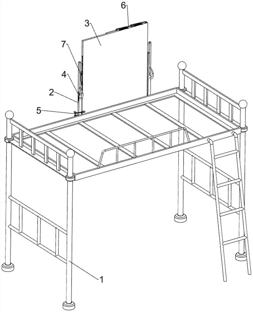
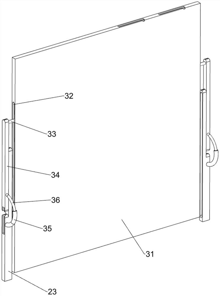
[0027] A student bed with a simple table, such as Figure 1-10 As shown, it includes a student bed body 1, a guide assembly 2, a placement assembly 3 and a clamping assembly 4. The student bed body 1 is provided with a guide assembly 2 that guides by sliding. The placement component 3 is placed in a way, and the placement component 3 is provided with a clamping component 4 that is clamped by sliding.
[0028] When using the device, first adjust the position of the placement assembly 3 through the guide assembly 2. After completion, release the clamping assembly 4, and the placement assembly 3 will open accordingly. After use, close the placement assembly 3, and use the clamping assembly 4 to place Place component 3 and snap it tight.
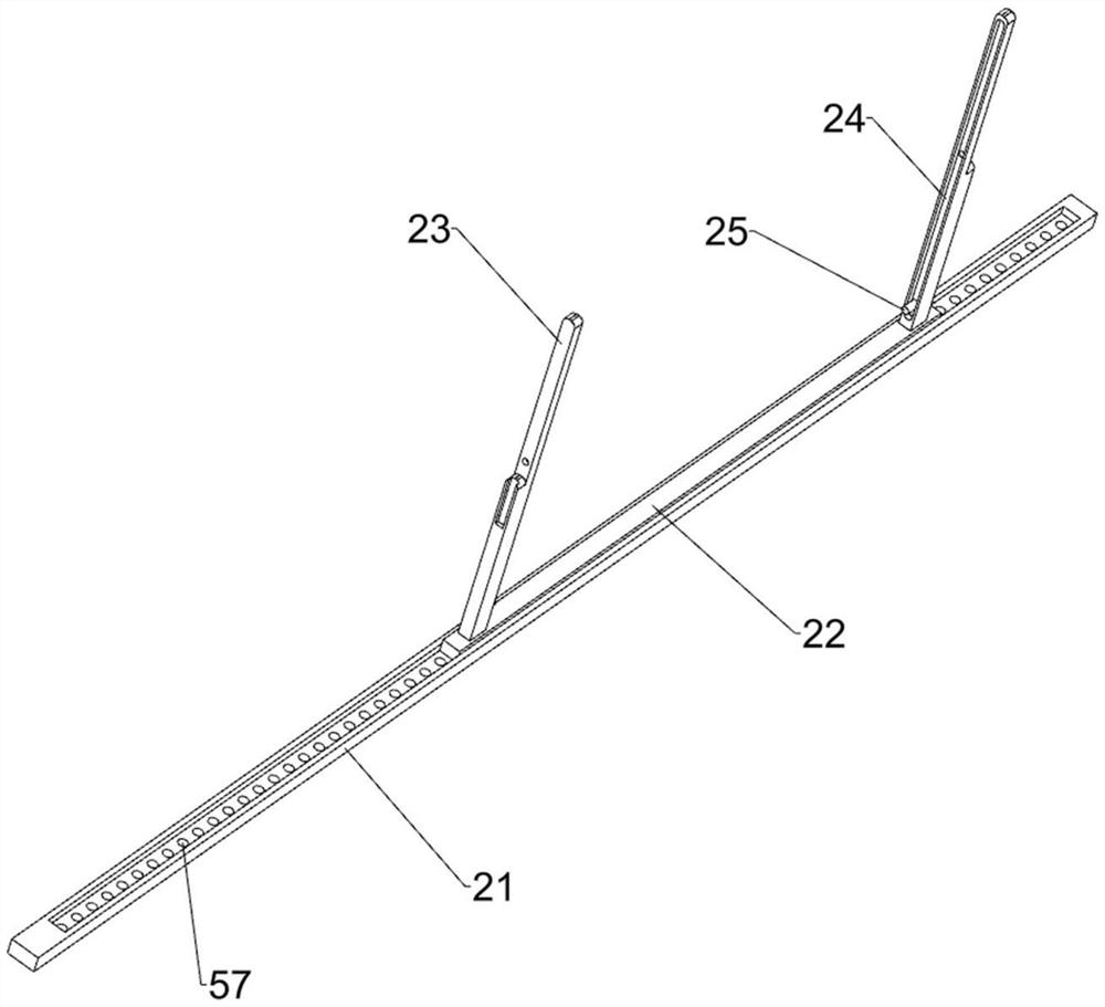
[0029] Such as figure 1 , figure 2 , image 3 , Figure 4 , Figure 6 and Figure 10 As shown, the guide assembly 2 includes a strip guide rail 21, a strip block 22, a mounting plate 23 and a first slider 25. Bar block 22, the left and ...
Embodiment 2
[0036] On the basis of Example 1, such as figure 1 , figure 2 and Figure 6 As shown, a fixed assembly 5 is also included, and the fixed assembly 5 includes a first guide sleeve 51, an insertion rod 52, a third spring 53, a contact plate 54, a first rotating rod 55 and a special-shaped block 56, and the mounting plate 23 on the left A first guide sleeve 51 is arranged on the outer side of the lower part, and an insertion rod 52 is slidably arranged inside the first guide sleeve 51. A third spring 53 is wound between the insertion rod 52 and the first guide sleeve 51, and the third spring 53 is in tension. state, the upper part of the insertion rod 52 is provided with a contact plate 54, and the front side of the lower part of the mounting plate 23 on the left is rotatably provided with a first rotating rod 55. Special-shaped block 56, special-shaped block 56 cooperates with first rotating rod 55, has a row of through holes 57 on the strip guide rail 21, and through holes 57...
PUM
 Abstract
Description
Claims
Application Information
 - R&D
- Intellectual Property
- Life Sciences
- Materials
- Tech Scout
- Unparalleled Data Quality
- Higher Quality Content
- 60% Fewer Hallucinations
Browse by: Latest US Patents, China's latest patents, Technical Efficacy Thesaurus, Application Domain, Technology Topic, Popular Technical Reports.
© 2025 PatSnap. All rights reserved.Legal|Privacy policy|Modern Slavery Act Transparency Statement|Sitemap|About US| Contact US: help@patsnap.com


