
V-shaped conveying inner chamfering equipment and using method

A chamfering and equipment technology, applied in the field of spring processing, can solve the problems of poor economy, large space occupied by equipment, and adverse effects on product processing quality, so as to achieve the effect of ensuring the qualified rate and reducing the occupation

Inactive Publication Date: 2021-03-02
廖雪松
View PDF11 Cites 2 Cited by
  • Summary
  • Abstract
  • Description
  • Claims
  • Application Information

AI Technical Summary

Problems solved by technology

[0007] Aiming at the above-mentioned deficiencies in the prior art, the present invention provides a V-shaped conveying inner chamfering equipment to solve the problem that the existing spring processing equipment cannot automatically screen out unqualified springs when the springs are transported, especially Rejection when there is a specific processing requirement for the spring diameter on the detection line, it will affect the subsequent chamfering process of the spring, and have an adverse effect on the processing quality of the product, and the existing equipment occupies a large area, which is not conducive to the overall layout of the plant and the economy. Poor problem, the present invention also provides the use method of the V-shaped conveying inner chamfering equipment, which has the beneficial effect of screening and discharging unqualified springs

Method used


Image

  • V-shaped conveying inner chamfering equipment and using method
  • V-shaped conveying inner chamfering equipment and using method
  • V-shaped conveying inner chamfering equipment and using method

Examples


Embodiment 1

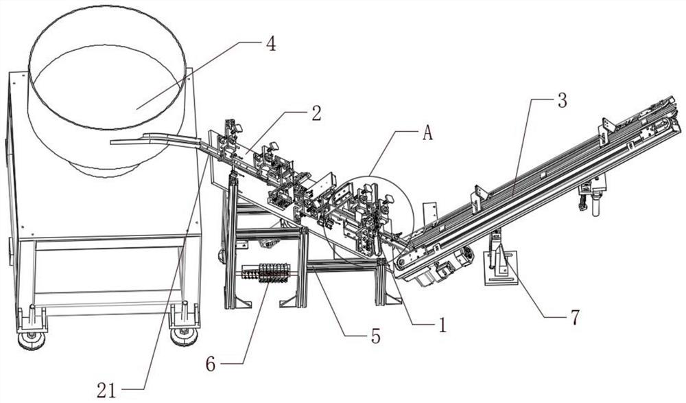
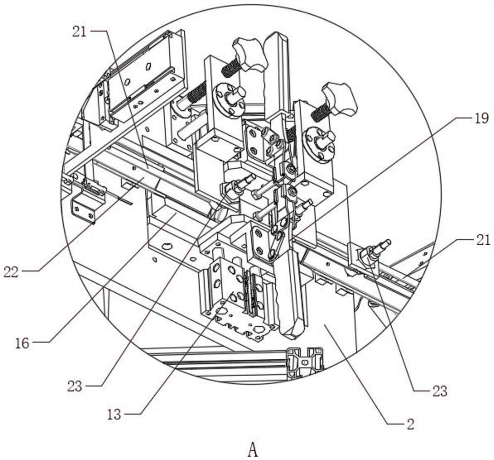
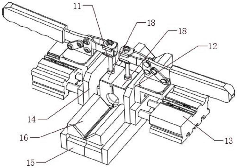
[0049] Such as Figure 1-6 As shown, the V-shaped conveying inner chamfering equipment of the present invention includes an outer diameter detection and discharge assembly 1, a downhill conveying line 2, a climbing conveying line 3, a feeding vibrating plate 4, an outer diameter detection and discharge assembly 1, a downhill The conveyor line 2, the climbing conveyor line 3, and the feeding vibrating plate 4 are all electrically connected to the solenoid valve 6, the tail of the downhill conveyor line 2 is overlapped with the head of the climb conveyor line 3, and the downhill conveyor line 2 is connected to the climber The slope conveying line 3 forms an included angle, the downhill conveying line 2 is connected with the upper part of the downhill support 5, the solenoid valve 6 is connected with the downhill support 5, the bottom of the climbing conveying line 3 is connected with the uphill adjustable support 7, and the downhill A guide assembly 21 is provided on the conveyi...

Embodiment 2

[0063] This embodiment is a further improvement of the previous embodiment, such as Figure 1-6 As shown, the V-shaped conveying inner chamfering equipment of the present invention includes an outer diameter detection and discharge assembly 1, a downhill conveying line 2, a climbing conveying line 3, a feeding vibrating plate 4, an outer diameter detection and discharge assembly 1, a downhill The conveyor line 2, the climbing conveyor line 3, and the feeding vibrating plate 4 are all electrically connected to the solenoid valve 6, the tail of the downhill conveyor line 2 is overlapped with the head of the climb conveyor line 3, and the downhill conveyor line 2 is connected to the climber The slope conveying line 3 forms an included angle, the downhill conveying line 2 is connected with the upper part of the downhill support 5, the solenoid valve 6 is connected with the downhill support 5, the bottom of the climbing conveying line 3 is connected with the uphill adjustable suppor...

Embodiment 3

[0079] This embodiment is a further improvement of the previous embodiment, such as Figure 1-6 As shown, the V-shaped conveying inner chamfering equipment of the present invention includes an outer diameter detection and discharge assembly 1, a downhill conveying line 2, a climbing conveying line 3, a feeding vibrating plate 4, an outer diameter detection and discharge assembly 1, a downhill The conveyor line 2, the climbing conveyor line 3, and the feeding vibrating plate 4 are all electrically connected to the solenoid valve 6, the tail of the downhill conveyor line 2 is overlapped with the head of the climb conveyor line 3, and the downhill conveyor line 2 is connected to the climber The slope conveying line 3 forms an included angle, the downhill conveying line 2 is connected with the upper part of the downhill support 5, the solenoid valve 6 is connected with the downhill support 5, the bottom of the climbing conveying line 3 is connected with the uphill adjustable suppor...


PUM


Abstract

The invention belongs to the technical field of spring machining, and particularly relates to V-shaped conveying inner chamfering equipment. The V-shaped conveying inner chamfering equipment comprisesan outer diameter detecting and discharging assembly, a downhill conveying line, a climbing conveying line and a feeding vibration disc which are all electrically connected with an electromagnetic valve; the tail portion of the downhill conveying line is in lap joint with the head portion of the climbing conveying line; an included angle is formed between the downhill conveying line and the climbing conveying line; the downhill conveying line is connected with the upper portion of a downhill support; the electromagnetic valve is connected with the downhill support; and the bottom of the climbing conveying line is connected with an uphill adjustable support. The V-shaped conveying inner chamfering equipment solves the problems that when existing spring machining equipment transports springs, unqualified springs cannot be automatically screened out, especially when unqualified springs are judged on a detection line with specific spring diameter machining requirements; a follow-up chamfering procedure of springs is affected; and the existing equipment is large in occupied space, so that overall arrangement of a plant is not facilitated, and the economical efficiency is poor.

Description

technical field [0001] The invention belongs to the technical field of spring processing, and in particular relates to a V-shaped conveying inner chamfering device and a using method. Background technique [0002] A spring is a mechanical part that uses elasticity to work. Parts made of elastic materials are deformed under the action of external force, and return to their original shape after the external force is removed. Spring is one of the basic mechanical parts, and it is widely used in various fields of national economy and social life. Therefore, to optimize the spring processing equipment-spring forming machine, improve its equipment structure, and make it more reasonable is the common wish of equipment manufacturers and spring manufacturers, especially in the field of chamfering the two ends of the spring. The spring chamfering machine is used. The chamfering machine is a small precision machine tool specially used for chamfering of mold manufacturing, hardware mac...

Claims


Application Information

Patent Timeline
Patent Type & Authority Applications(China)
IPC IPC(8): B07C5/06B07C5/08B07C5/02B07C5/36B07C5/38
CPCB07C5/06B07C5/08B07C5/02B07C5/362B07C5/38
Inventor 廖雪松
Owner 廖雪松
Learn More