Disc type motor with ultra-low inertia
A disk motor, ultra-low inertia technology, applied in the direction of electrical components, electromechanical devices, circuit devices, etc., can solve the problems of slow start, large rotor inertia, slow braking, etc., to achieve reduced inertia, light weight, high speed Effect
- Summary
- Abstract
- Description
- Claims
- Application Information
AI Technical Summary
Problems solved by technology
Method used
Image
Examples
Embodiment 1
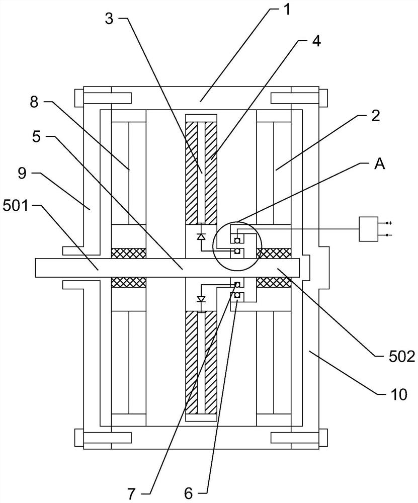
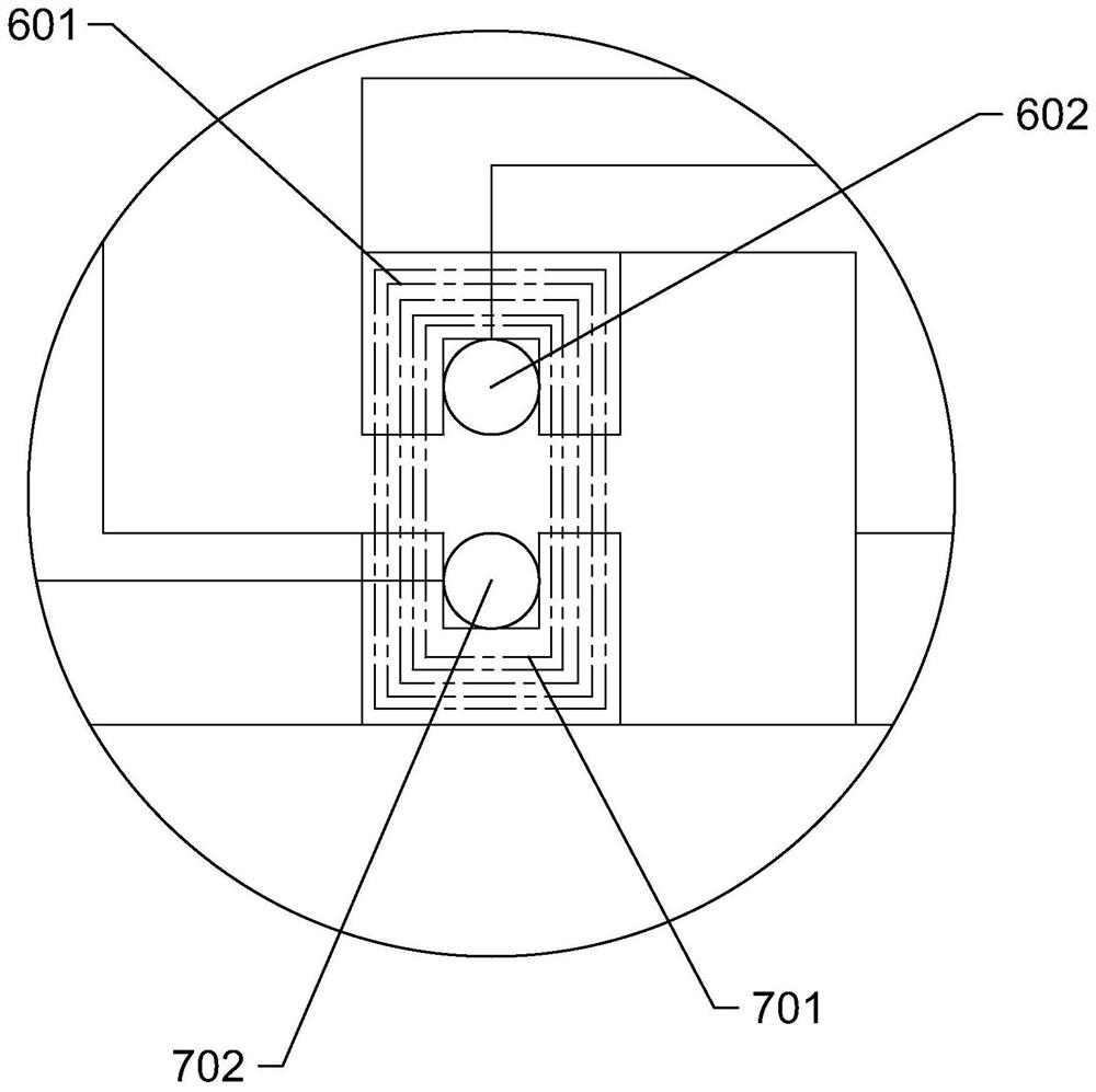
[0023] Such as figure 1 and 2 As shown, the ultra-low inertia disc motor includes a housing 1, a first stator 2 and a second stator 8 are fixedly arranged in the housing 1, and the first stator 2 and the second stator 8 are parallel and cooperate with each other. There is rotor 3. The rotor 3 is configured as a PCB board, and the rotor 3 includes a coil winding area 4 , and the coil winding area 4 generates magnetic induction lines perpendicular to the rotor 3 after being energized. Wherein the first stator 2, the second stator 8 and the rotor 3 are all arranged in a disk shape, so that the whole machine is flatter, smaller in size and higher in speed, and the coil winding area 4 is connected with the first stator 2 and the second stator 8 parallel. Both the first stator 2 and the second stator 8 include a conductive material part and a magnetic permeable material part, and the conductive material part is arranged close to the rotor 3 . The rotor 3 is fixedly connected to ...
Embodiment 2
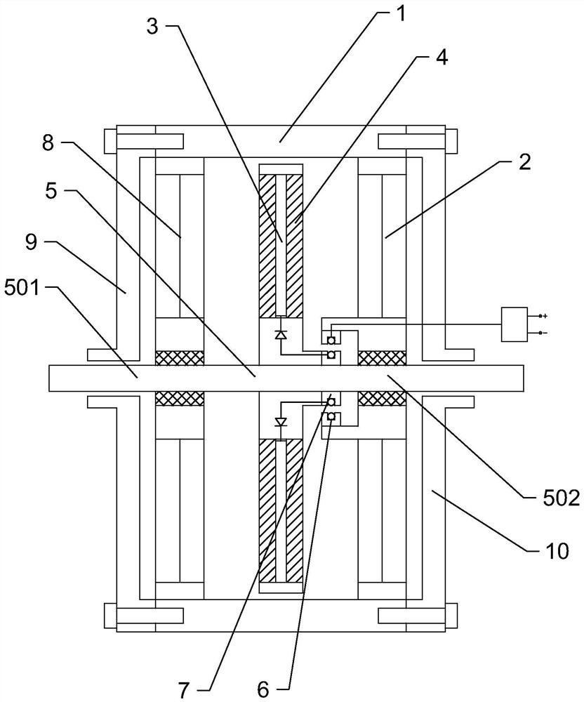
[0028] Such as image 3 As shown, the ultra-low inertia disc motor includes a housing 1, a first stator 2 and a second stator 8 are fixedly arranged in the housing 1, and the first stator 2 and the second stator 8 are parallel and cooperate with each other. There is rotor 3. The rotor 3 is configured as a PCB board, and the rotor 3 includes a coil winding area 4 , and the coil winding area 4 generates magnetic induction lines perpendicular to the rotor 3 after being energized. Wherein the first stator 2, the second stator 8 and the rotor 3 are all arranged in a disk shape, so that the whole machine is flatter, smaller in size and higher in speed, and the coil winding area 4 is connected with the first stator 2 and the second stator 8 parallel. Both the first stator 2 and the second stator 8 include a conductive material part and a magnetic permeable material part, and the conductive material part is arranged close to the rotor 3 . The rotor 3 is fixedly connected to the rot...
Embodiment 3
[0033] Such as Figure 4 As shown, the ultra-low inertia disc motor includes a housing 1 , and a first stator 2 is fixedly arranged in the housing 1 . The first stator 2 is matched with a rotor 3 in parallel, and one stator is matched with a rotor 3 . The rotor 3 is configured as a PCB board, and the rotor 3 includes a coil winding area 4 , and the coil winding area 4 generates magnetic induction lines perpendicular to the rotor 3 after being energized. Wherein the first stator 2 and the rotor 3 are both arranged in a disc shape, which makes the whole machine flatter, smaller in size and higher in speed, and the coil winding area 4 is parallel to the first stator 2 . The first stator 2 includes a conductive material part and a magnetic permeable material part, and the conductive material part is arranged close to the rotor 3 . The rotor 3 is fixedly connected to the rotating shaft 5. The rotating shaft 5 includes a first half shaft 501 and a second half shaft 502. The first s...
PUM
 Abstract
Description
Claims
Application Information
 - R&D Engineer
- R&D Manager
- IP Professional
- Industry Leading Data Capabilities
- Powerful AI technology
- Patent DNA Extraction
Browse by: Latest US Patents, China's latest patents, Technical Efficacy Thesaurus, Application Domain, Technology Topic, Popular Technical Reports.
© 2024 PatSnap. All rights reserved.Legal|Privacy policy|Modern Slavery Act Transparency Statement|Sitemap|About US| Contact US: help@patsnap.com


