Cooling and noise-reducing case

A cooling and noise reduction, casing technology, applied in the casing/cover/support, electromechanical device, cooling/ventilation device, etc., can solve the problems of inconvenient motor installation, time-consuming and laborious, etc. Good noise cancellation effect

Inactive Publication Date: 2021-02-26
ZHANGQIU FENGYUAN MACHINERY
View PDF1 Cites 0 Cited by
  • Summary
  • Abstract
  • Description
  • Claims
  • Application Information

AI Technical Summary

Problems solved by technology

[0004] The purpose of the present invention is to solve the disadvantages in the prior art that the casing is composed of an outer casing and an inner casing. It is very inconvenient to install the motor inside the inner casing. A casing for reducing temperature and noise

Method used


Image

  • Cooling and noise-reducing case
  • Cooling and noise-reducing case
  • Cooling and noise-reducing case

Examples


Embodiment 1

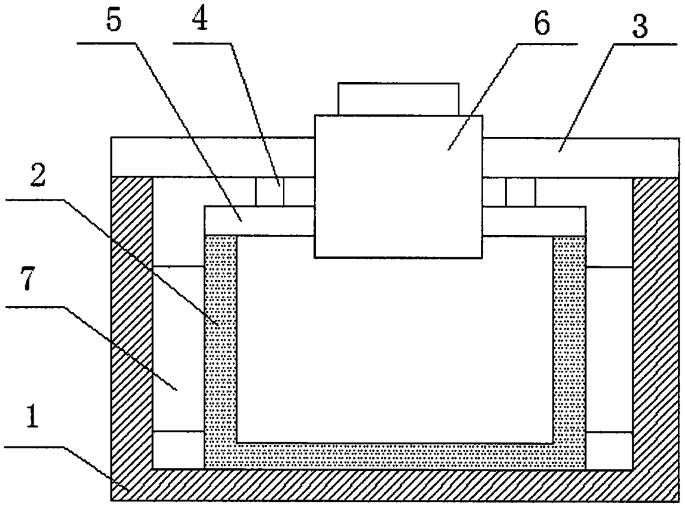
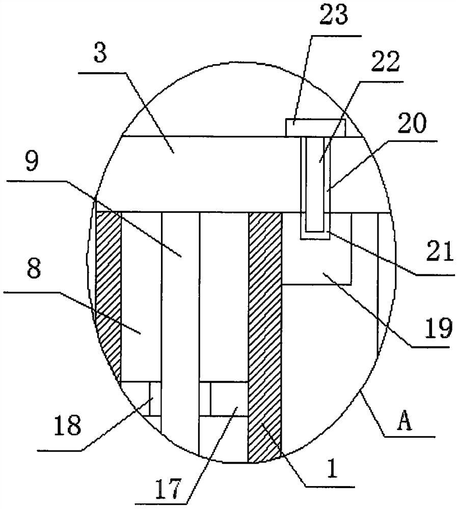
[0021] refer to Figure 1-3 , a casing for reducing temperature and noise, comprising an outer casing 1 and an inner casing 2, one side and the top side of the outer casing 1 and the inner casing 2 are all openings, and the inner casing 2 is slidably installed on the outer casing 1 On the inner wall of the bottom side, an outer cover plate 3 is placed on the top side of the outer shell 1, two connecting rods 4 are fixedly installed on the bottom side of the outer cover plate 3, and the same inner cover plate is fixedly installed on the bottom ends of the two connecting rods 4 5. The inner cover 5 is compatible with the top side of the inner shell 2, and the outer shell 1 is provided with a mounting groove 8, and a moving rod 9 is installed in the mounting groove 8, and the top end of the moving rod 9 is fixedly installed on the outer cover 3 On the bottom side of the mounting groove 8, a mounting hole 10 is opened on one side of the inner wall, and a gear 11 is installed in th...

Embodiment 2

[0027] refer to Figure 1-3 , a casing for reducing temperature and noise, comprising an outer casing 1 and an inner casing 2, one side and the top side of the outer casing 1 and the inner casing 2 are all openings, and the inner casing 2 is slidably installed on the outer casing 1 On the inner wall of the bottom side, an outer cover plate 3 is placed on the top side of the outer shell 1, and two connecting rods 4 are fixedly installed on the bottom side of the outer cover plate 3 by welding, and the bottom ends of the two connecting rods 4 are fixedly installed by welding There is the same inner cover plate 5, the inner cover plate 5 is adapted to the top side of the inner casing 2, the outer casing 1 is provided with a mounting groove 8, and a moving rod 9 is movably installed in the mounting groove 8, and the top of the moving rod 9 It is fixedly installed on the bottom side of the outer cover plate 3 by welding, and a mounting hole 10 is opened on the inner wall of one sid...


PUM


Abstract

The invention belongs to the technical field of motor shells, and particularly relates to a cooling and noise-reducing case. Aiming at overcoming the defects that an existing machine shell is formed by combining an outer shell body and an inner shell body, a motor is very inconvenient to install in the inner shell body, the motor can only be installed from an opening, and time and labor are wasted, the invention proposes the following scheme that the case comprises an outer shell and an inner shell; one side and the top side of the outer shell and one side and the top side of the inner shell are open; the inner shell is installed on the inner wall of the bottom side of the outer shell in a sliding mode, an outer cover plate is placed on the top side of the outer shell, two connecting rodsare fixedly installed on the bottom side of the outer cover plate, and the same inner cover plate is fixedly installed at the bottom ends of the two connecting rods. The case is simple in structure, the multiple heat conduction plates and the sound absorption cotton are arranged to enable the motor shell to be good in cooling, heat dissipation, noise reduction and noise reduction effects, after the outer cover plate is lifted upwards, the inner shell with the opening in the top side is pushed out of the outer shell, a motor does not need to be operated in the narrow outer shell during installation, and installation is quite convenient.

Description

technical field [0001] The invention relates to the technical field of motor casings, in particular to a cooling and noise-reducing casing. Background technique [0002] The main causes of motor noise are the noise caused by the imbalance of the rotor, the noise caused by the bearing and the noise caused by mechanical processing factors. For example, the machining accuracy of the casing, stator, rotor, and shaft is relatively rough. It may lead to the superposition of mechanical noise factors, which will increase the noise of the motor. The current motor casing generally has a relatively simple structure, which cannot be well reduced for noise, which affects the use. [0003] The patent with the publication number CN208489743U discloses a motor noise reduction casing, including a first casing, a second casing and a noise reduction mechanism, the bottom of the first casing is fixedly provided with a support base, the first casing and the second The shells are both rectangula...

Claims


Application Information

Patent Timeline
IPC IPC(8): H02K5/04H02K9/22H02K5/24
CPCH02K5/04H02K5/24H02K9/22
Inventor 景奉国潘荣常张学飞
Owner ZHANGQIU FENGYUAN MACHINERY
Why Eureka
Try Eureka