Fixing cover for double-wire clamp

A technology of double wire clamp and fixed cover, which is applied in cable installation, cable suspension device, overhead installation, etc. It can solve the problems of poor tightness of suspension wire clamp, inability to reduce accident losses, difficulty in providing sufficient clamping force, etc.

Pending Publication Date: 2021-02-26
XINYANG POWER SUPPLY OF HENAN ELECTRIC POWER CORP
View PDF0 Cites 1 Cited by
  • Summary
  • Abstract
  • Description
  • Claims
  • Application Information

AI Technical Summary

Problems solved by technology

[0002] In the erection of ultra-high voltage transmission lines, in order to suppress corona discharge and reduce line reactance, the method of split wires is usually used for construction, that is, each phase wire is composed of two or more wires with smaller cross-sections. Using split wires is equivalent to Enlarging the diameter of the wire will not easily produce corona, increase the power transmission capacity, and improve the stability of the line. When the transmission line passes through the tension tower, in order to keep the charged wire and the conductive part of the tower at a sufficient electrical distance, usually The tension clamps on both sides of the line tower are connected by the drainage wire, which is commonly known as "jumper wire". The tightness of the wire clamp is poor, and it is difficult to completely fix the drainage wire. When affected by natural wind or rain and snow, friction between the drainage wire and the suspension wire clamp is easy to occur, causing damage to the drainage wire. When an accident occurs on the transmission line and the wire is broken, Dangling clamps are also difficult to provide sufficient clamping force to mitigate damage caused by accidents

Method used


Image

  • Fixing cover for double-wire clamp
  • Fixing cover for double-wire clamp
  • Fixing cover for double-wire clamp

Examples


Embodiment 1

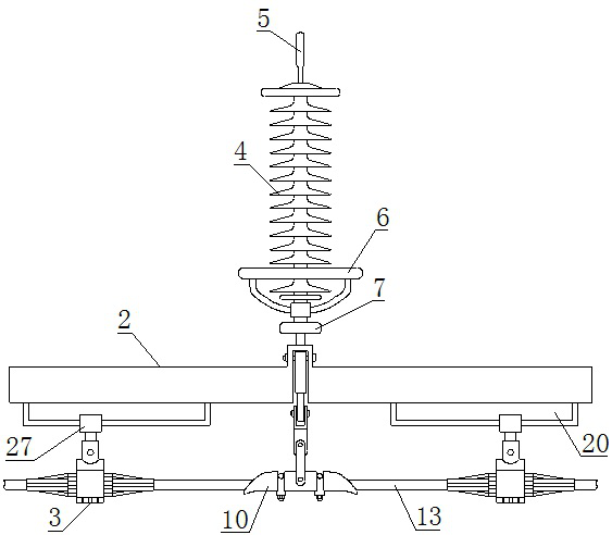
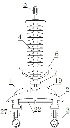
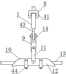
[0030] Such as Figure 1-12 As shown, the fixed cover for the double wire clamp includes a chassis 1, a cover plate 2 and a clamping seat 3, a fixed block 7 is arranged above the chassis 1, and an insulator string 4 is arranged above the fixed block 7, so A clamping plate 8 is provided below the fixed block 7, a through hole A39 is provided on the upper side of the chassis 1, a clamp shaft 41 is provided inside the through hole A39, and through holes are provided on both sides of the through hole A39. B40, the lower side of the chassis 1 is provided with a lead-out head 43, the lower end of the lead-out head 43 is provided with a traction seat 9, the lower side of the traction seat 9 is provided with a traction plate 42, and the traction plate 42 A suspension clamp 10 is provided below, a hanging ring 11 is provided on the upper side of the suspension clamp 10, a base 12 is provided on the lower side of the hanging ring 11, and a hoop 16 is provided on the inner side of the ba...

Embodiment 2

[0039] Such as Figure 1-12 As shown, the fixed cover for the double wire clamp includes a chassis 1, a cover plate 2 and a clamping seat 3, a fixed block 7 is arranged above the chassis 1, and an insulator string 4 is arranged above the fixed block 7, so A clamping plate 8 is provided below the fixed block 7, a through hole A39 is provided on the upper side of the chassis 1, a clamp shaft 41 is provided inside the through hole A39, and through holes are provided on both sides of the through hole A39. B40, the lower side of the chassis 1 is provided with a lead-out head 43, the lower end of the lead-out head 43 is provided with a traction seat 9, the lower side of the traction seat 9 is provided with a traction plate 42, and the traction plate 42 A suspension clamp 10 is provided below, a hanging ring 11 is provided on the upper side of the suspension clamp 10, a base 12 is provided on the lower side of the hanging ring 11, and a hoop 16 is provided on the inner side of the ba...


PUM


Abstract

The invention relates to a fixing cover for a double-wire clamp, and the cover comprises a chassis, a cover plate and a clamping seat; an insulator string is arranged above the chassis, a traction seat is connected to a leading-out end on the lower side of the chassis, a suspension clamp is arranged on the lower side of the traction seat, a connecting seat is arranged on the outer side of the chassis, the cover plate is arranged on the lower side of the connecting seat, and a sliding rod is arranged below the cover plate; the distance between the sliding rods can be changed by rotating the screw rods, the lower sides of the sliding rods are connected with the clamping seats, and the inner twisted wires, the tightening rings and the outer twisted wires are sequentially wound on the outer sides of the parts, making contact with the clamping seats, of the wires, so large clamping force can be provided for the wires; the positions of the sliding rod and the sliding base are adjusted, the clamping base is fastened to the wire in a buckled mode, and under the combined action of the suspension clamp and the clamping base, accidents caused by wire damage to a power transmission line can beprevented. The clamping device has the advantages of being convenient to install, wide in applicability, good in clamping effect and high in protection capacity.

Description

technical field [0001] The invention belongs to the technical field of electric power protection equipment, and in particular relates to a fixed cover for double wire clips. Background technique [0002] In the erection of ultra-high voltage transmission lines, in order to suppress corona discharge and reduce line reactance, the method of split wires is usually used for construction, that is, each phase wire is composed of two or more wires with smaller cross-sections. Using split wires is equivalent to Enlarging the diameter of the wire will not easily produce corona, increase the power transmission capacity, and improve the stability of the line. When the transmission line passes through the tension tower, in order to keep the charged wire and the conductive part of the tower at a sufficient electrical distance, usually The tension clamps on both sides of the line tower are connected by the drainage wire, which is commonly known as "jumper wire". The tightness of the wire...

Claims


Application Information

Patent Timeline
IPC IPC(8): H02G7/05
CPCH02G7/053H02G7/05
Inventor 林德山林家烨姚竟成王鹏王发义魏继承刘承惠张全生严建邦
Owner XINYANG POWER SUPPLY OF HENAN ELECTRIC POWER CORP
Why Eureka
Try Eureka