Self-floating spatial spiral net-shaped drainage device and working method

A drainage device and self-floating technology, which is applied in the direction of infrastructure engineering, construction, soil protection, etc., can solve the problem of gradual clogging of plastic drainage boards and drainage failure, the decrease of the permeability coefficient of the vacuum filter membrane, and the drainage path of the drainage belt Single and other problems, to achieve fine control of drainage path and treatment range, increase vertical treatment range, and increase the effect of treatment space scale

Pending Publication Date: 2022-08-09
NANJING FORESTRY UNIV
View PDF0 Cites 0 Cited by
  • Summary
  • Abstract
  • Description
  • Claims
  • Application Information

AI Technical Summary

Problems solved by technology

[0003] The search found that Zhao Dong analyzed several commonly used foundation treatment methods in "Comparison and Selection of Subgrade Treatment Methods for Filled Soil Roads", and concluded that the use of plastic drainage boards for foundation treatment is suitable for projects with thick silt layers, but not Solve the problem of gradual clogging and drainage failure during the drainage process of plastic drainage boards; Wang Ruchong, Wang Rongpeng, and Sui Yu, in the "Blooding Test of Plastic Drainage Boards for Dredging and Filling Soil", compared the permeability coefficient of membranes before and after the membrane silting test It was found that the permeability coefficient of the vacuum filter membrane decreased significantly, and the smaller the equivalent pore size of the filter membrane, the more serious the clogging situation
[0004] Therefore, the existing technology is difficult to solve the problems of single drainage path, small treatment range, easy blockage and drainage failure in traditional drainage belts

Method used


Image

  • Self-floating spatial spiral net-shaped drainage device and working method
  • Self-floating spatial spiral net-shaped drainage device and working method
  • Self-floating spatial spiral net-shaped drainage device and working method

Examples


Embodiment Construction

[0032] The present invention will be further described below with reference to the accompanying drawings and embodiments.

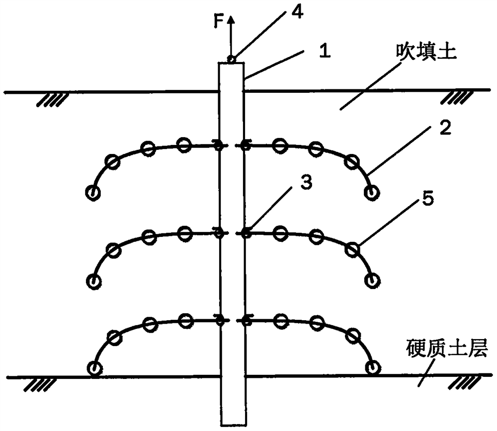
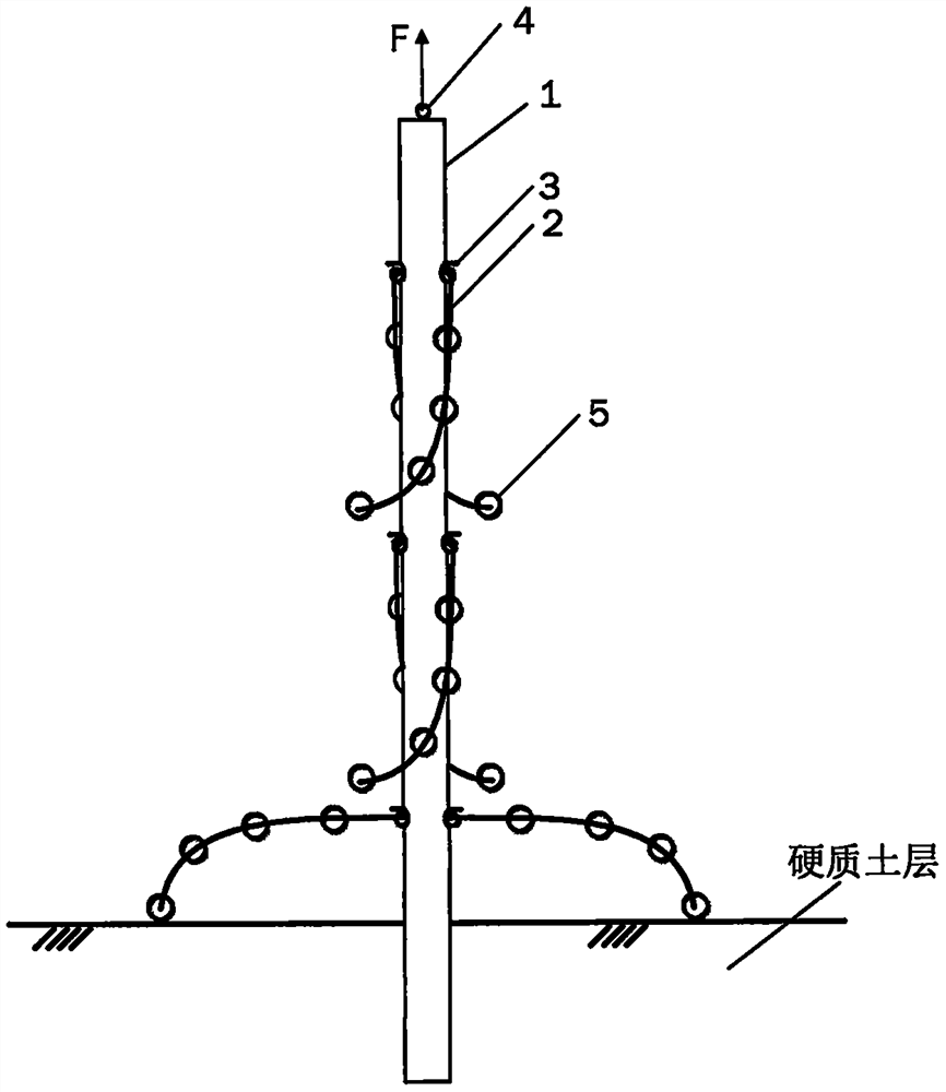
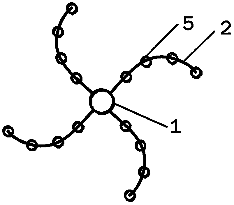
[0033] like Figure 1-Figure 4 As shown, the self-floating spiral mesh drainage device includes a main drainage belt 1, a drainage branch 2, a stopper 3, a hanging hole 4, and a floating ball 5;

[0034] The main drainage belt 1 is a traditional flexible drainage belt, which can transmit the moisture in the soil to the top and discharge; , a multi-layer drainage branch 2 is arranged in the middle, the drainage branch 2 is connected with the internal pores of the main drainage belt 1, and the water in the drainage branch can be discharged through the top of the main drainage belt;

[0035] The drainage branch 2 is an arc-shaped rigid tubular structure, and the surface is covered with geotextile, which is water permeable; 3 to 5 floating balls 5 are attached to each drainage branch, which are equally spaced on the drainage branch, and rely on the filling s...


PUM


Abstract

The invention provides a self-floating type spatial spiral net-shaped drainage device and a working method. The device comprises a main drainage belt, drainage branches, limiters, hanging holes and floating balls. The main drainage belt is a traditional flexible drainage belt; the drainage branches are of arc-shaped hard tubular structures, geotechnical cloth wraps the surfaces of the drainage branches, the drainage branches have water permeability, and water in the drainage branches can be drained through the top of the main drainage belt; the floating balls are equidistantly distributed on the drainage branches; in a dredger fill construction site, the lower end of the main drainage belt is pre-buried in a hard soil layer to be fixed, and in the rising process of dredger fill, the floating balls drive the drainage branches to rise by means of buoyancy brought by the dredger fill, so that the whole body is of a spatial spiral net structure; compared with a traditional drainage belt, the device has the advantages that transverse and vertical treatment ranges are increased, the length of a drainage path is effectively reduced, the treatment space scale of the same drainage belt is increased, and the overall treatment range and treatment efficiency of a whole drainage device system are guaranteed.

Description

technical field [0001] The invention relates to the technical field of foundation treatment and consolidation, in particular to a self-floating space spiral mesh drainage device suitable for reclamation foundation treatment and a working method. Background technique [0002] Blow fill is one of the more common artificial fills. It is mainly due to the remediation or dredging of river waterways, or the need to fill or fill up certain areas near the river due to industrial and agricultural production. High-pressure mud pumps are used to excavate dredgers The silt and sand are discharged to the areas that need to be raised and the silt accumulation area through the mud conveying pipe, and a large piece of artificial fill is formed after sedimentation and discharge. The special causes of blowing and filling have special engineering characteristics, such as unevenness, weak water permeability, poor drainage consolidation, under-consolidation, high compression, low bearing capacit...

Claims


Application Information

Patent Timeline
Patent Type & Authority Applications(China)
IPC IPC(8): E02D3/10
CPCE02D3/10E02D2250/0053
Inventor 刘成朱益陈亮羽刘艳军王海波
Owner NANJING FORESTRY UNIV
Why Eureka
Try Eureka