
Dielectric filter strong coupling input and output structure

A dielectric filter, input and output technology, applied in waveguide-type devices, electrical components, circuits, etc., can solve the problems of small coupling blind holes and frequency modulation blind holes, difficult production, broken holes, etc., to reduce the difficulty of production and manufacturing, Through hole processing is easy, reducing the effect of input and output coupling

Pending Publication Date: 2021-02-26
JIANGSU HENGXIN TECH CO LTD
View PDF0 Cites 0 Cited by
  • Summary
  • Abstract
  • Description
  • Claims
  • Application Information

AI Technical Summary

Problems solved by technology

With the expansion of the frequency band and application range, such as dielectric duplexers, etc., the required operating bandwidth is as high as 400-800MHz, and stronger input and output coupling is required, resulting in too small a gap between the coupling blind hole and the frequency modulation blind hole, which is easy to cause damage. hole, difficult to produce

Method used


Image

  • Dielectric filter strong coupling input and output structure
  • Dielectric filter strong coupling input and output structure
  • Dielectric filter strong coupling input and output structure

Examples


Embodiment 1

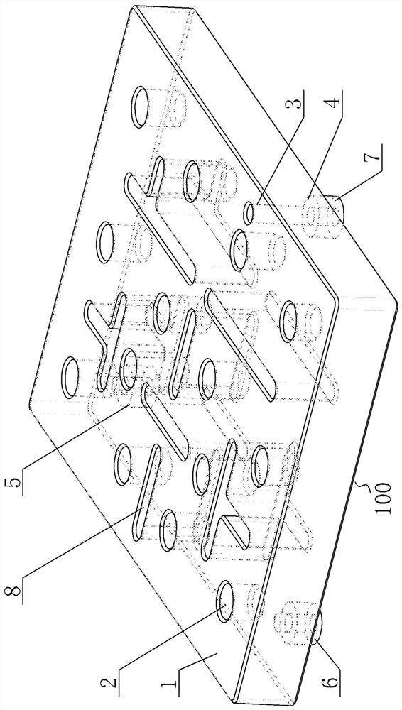
[0027] Embodiment one, see image 3 , which is a dielectric duplexer 100 using this input-output structure, which includes a ceramic dielectric substrate (tap cavity 1), a frequency blind hole (FM blind hole 2) located on the upper surface of the substrate, RX receiving port 5, and TX transmitting port 6 , ANT antenna port 7, a coupling slot 8 penetrating through the substrate, the surface of the dielectric substrate, the inner surface of the frequency hole, and the side of the coupling slot are all covered with a layer of conductive metal layer. This dielectric duplexer works in the 1805-1880 / 2110-2170MHz frequency band, and its ANT port needs to cover 1805-2170MHz, with a working bandwidth of 365MHz. If the existing blind hole input and output structure is used, the coupling blind hole and FM blind hole The gap between them will be less than 0.5mm, and holes will easily occur. Therefore, the input and output structure of the ANT port of the dielectric duplexer adopts the st...


PUM


Abstract

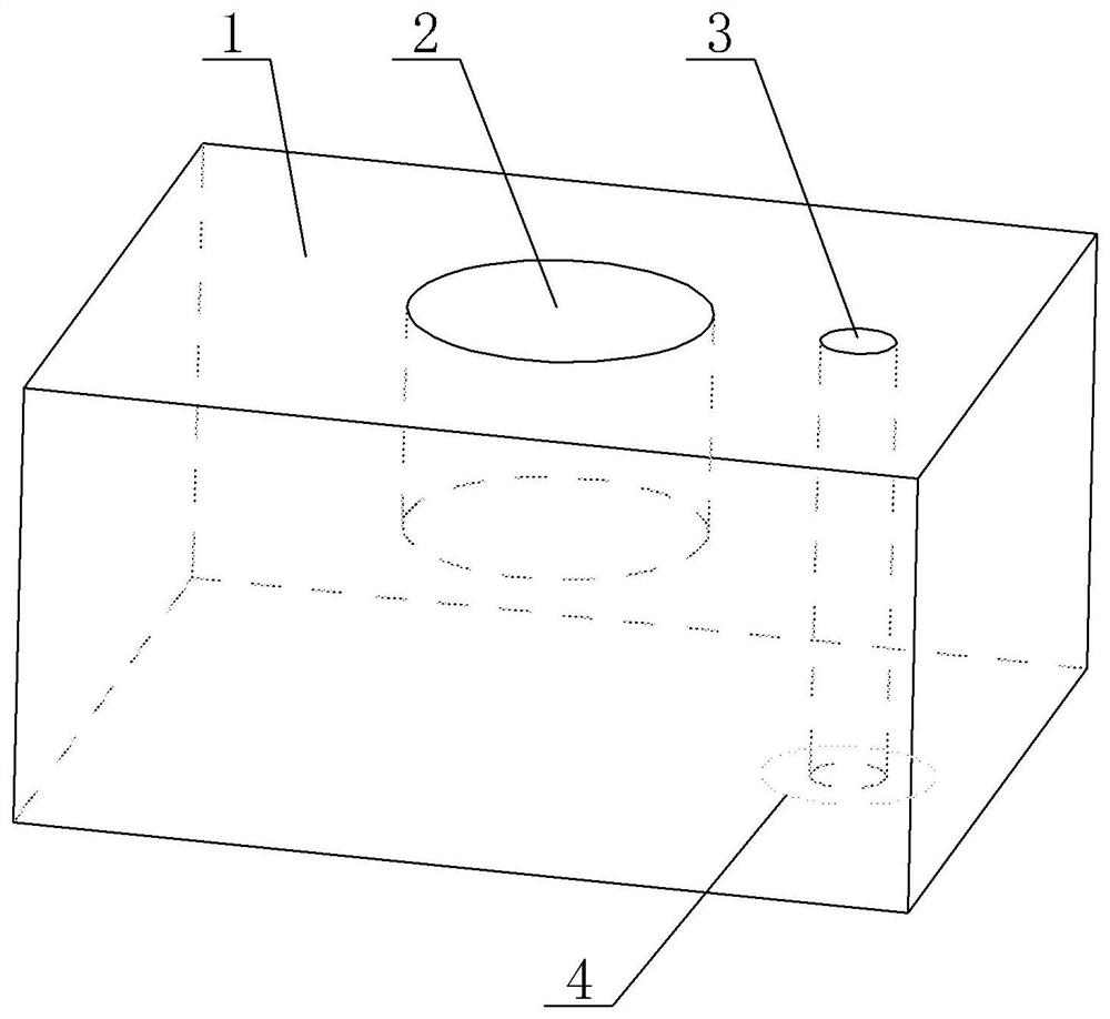
The invention provides a strong coupling input and output structure of a dielectric filter, which solves the input and output problems of the dielectric filter with a large working bandwidth and reduces the production and manufacturing difficulty at the same time. The tap comprises a tap cavity, a concave frequency modulation blind hole is formed in the upper surface of the tap cavity, a couplingthrough hole penetrating through the tap cavity in the thickness direction is further formed in the upper surface of the tap cavity, the frequency modulation blind hole is not communicated with the coupling through hole, and a gap is formed between the frequency modulation blind hole and the coupling through hole. The upper surface or the lower surface of the coupling through hole is provided withan annular groove area, namely a feed ring, which is concentric with the coupling through hole, the other surfaces of the tap cavity except the area of the feed ring are coated with conductive layers, the tap cavity is made of a ceramic medium or a high polymer material, and an electromagnetic wave signal is input or output through the feed ring.

Description

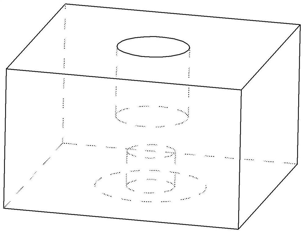
technical field [0001] The invention relates to the technical field of dielectric filters, in particular to a strong coupling input-output structure of a dielectric filter. Background technique [0002] With the development of 5G mobile communication technology, miniaturization and integration have become the development trend of communication equipment. The filter is one of the main functional components of 5G base station equipment, which is responsible for selecting electromagnetic waves of specific frequencies. Ceramic dielectric filters have become the mainstream technology of 5G filters due to their small size, light weight, and easy SMT (Surface Mount Technology) surface mount. At present, the working bandwidth of the ceramic dielectric filter is about 150MHz ~ 250MH, and the commonly used input and output structure is the coupling blind hole, such as figure 1 , the principle is that electric field coupling (capacitive coupling) is formed between the coupling blind ...

Claims


Application Information

Patent Timeline
Patent Type & Authority Applications(China)
IPC IPC(8): H01P1/20
CPCH01P1/2002
Inventor 蔡辉赵虎戴超周骑
Owner JIANGSU HENGXIN TECH CO LTD
Learn More