A method of using a die-cut hole defect detection device
A detection device, die-cut hole technology, applied in the direction of measuring devices, optical devices, instruments, etc., can solve the problems of reducing output, reducing production efficiency, low efficiency, etc., and achieve the effect of improving accuracy and improving production efficiency
- Summary
- Abstract
- Description
- Claims
- Application Information
AI Technical Summary
Problems solved by technology
Method used
Image
Examples
Embodiment 1
[0064] Provided is a method for using a device for detecting defective die-cutting holes, comprising the following steps:
[0065] (1) Put the product on the surface of the base, adjust the position of the fixed sliding limit block through the sliding limit block, and stabilize the position of the product in and out;
[0066] (2) Adjust the positions of the first moving rod, the second moving rod, the third moving rod, and the sensor bracket, so that the detection light spot falls directly above the detection hole;
[0067] (3) Adjust the height of the sensor, so that the difference between good and bad inductive values can be discriminated greatly;
[0068] (4) The defective die-cutting hole detection device is turned on and used.
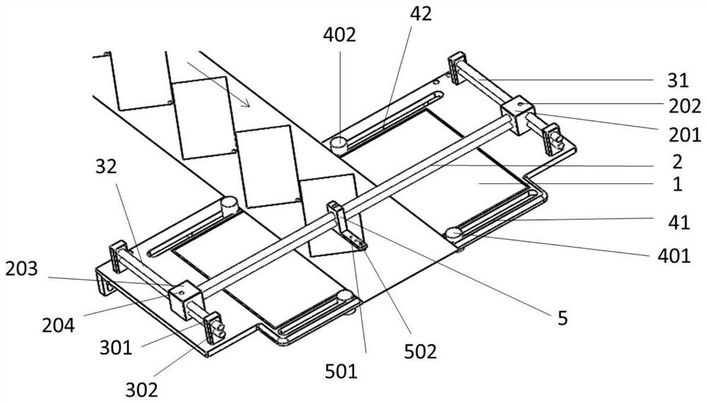
[0069] The die-cutting hole defect detection device at least includes: a base 1 , a first shift rod 2 , a second shift rod 31 , a third shift rod 32 , a first limit slot 41 , a second limit slot 42 , and a sensor bracket 5 The two ends of the ...
Embodiment 2
[0079] Provided is a method for using a device for detecting defective die-cutting holes, comprising the following steps:
[0080] (1) Put the product on the surface of the base, adjust the position of the fixed sliding limit block through the sliding limit block, and stabilize the position of the product in and out;
[0081] (2) Adjust the positions of the first moving rod, the second moving rod, the third moving rod, and the sensor bracket, so that the detection light spot falls directly above the detection hole;
[0082] (3) Adjust the height of the sensor, so that the difference between good and bad inductive values can be discriminated greatly;
[0083] (4) The defective die-cutting hole detection device is turned on and used.
[0084] The die-cutting hole defect detection device at least includes: a base 1 , a first shift rod 2 , a second shift rod 31 , a third shift rod 32 , a first limit slot 41 , a second limit slot 42 , and a sensor bracket 5 The two ends of the ...
Embodiment 3
[0094] Provided is a method for using a device for detecting defective die-cutting holes, comprising the following steps:
[0095] (1) Put the product on the surface of the base, adjust the position of the fixed sliding limit block through the sliding limit block, and stabilize the position of the product in and out;
[0096] (2) Adjust the positions of the first moving rod, the second moving rod, the third moving rod, and the sensor bracket, so that the detection light spot falls directly above the detection hole;
[0097] (3) Adjust the height of the sensor, so that the difference between good and bad inductive values can be discriminated greatly;
[0098] (4) The defective die-cutting hole detection device is turned on and used.
[0099] The die-cutting hole defect detection device at least includes: a base 1 , a first shift rod 2 , a second shift rod 31 , a third shift rod 32 , a first limit slot 41 , a second limit slot 42 , and a sensor bracket 5 The two ends of the ...
PUM
 Abstract
Description
Claims
Application Information
 - R&D
- Intellectual Property
- Life Sciences
- Materials
- Tech Scout
- Unparalleled Data Quality
- Higher Quality Content
- 60% Fewer Hallucinations
Browse by: Latest US Patents, China's latest patents, Technical Efficacy Thesaurus, Application Domain, Technology Topic, Popular Technical Reports.
© 2025 PatSnap. All rights reserved.Legal|Privacy policy|Modern Slavery Act Transparency Statement|Sitemap|About US| Contact US: help@patsnap.com

