
Hydraulic brake system and method

A technology of hydraulic braking and conventional braking, which is applied in the direction of braking safety systems, brakes, braking transmission devices, etc., can solve the problems that the brake pedal force is unfavorable to vehicle control, limit the upper limit of the driver's braking force, etc., and avoid braking. The effect of a sudden increase in power

Active Publication Date: 2021-02-26
DONGFENG MOTOR CORP HUBEI
View PDF5 Cites 6 Cited by
  • Summary
  • Abstract
  • Description
  • Claims
  • Application Information

AI Technical Summary

Problems solved by technology

In an emergency situation, the sudden increase in brake pedal force is not conducive to vehicle control, and also limits the upper limit of braking force that the driver can achieve

Method used


Image

  • Hydraulic brake system and method
  • Hydraulic brake system and method
  • Hydraulic brake system and method

Examples


Embodiment Construction

[0055]Reference will now be made in detail to specific embodiments of the invention, examples of which are illustrated in the accompanying drawings. While the invention will be described in conjunction with specific embodiments, it will be understood that it is not intended to limit the invention to the described embodiments. On the contrary, it is intended to cover alterations, modifications and equivalents as included within the spirit and scope of the invention as defined by the appended claims. It should be noted that the method steps described here can all be realized by any functional block or functional arrangement, and any functional block or functional arrangement can be realized as a physical entity or a logical entity, or a combination of both.

[0056] In order to enable those skilled in the art to better understand the present invention, the present invention will be further described in detail below in conjunction with the accompanying drawings and specific embod...


PUM


Abstract

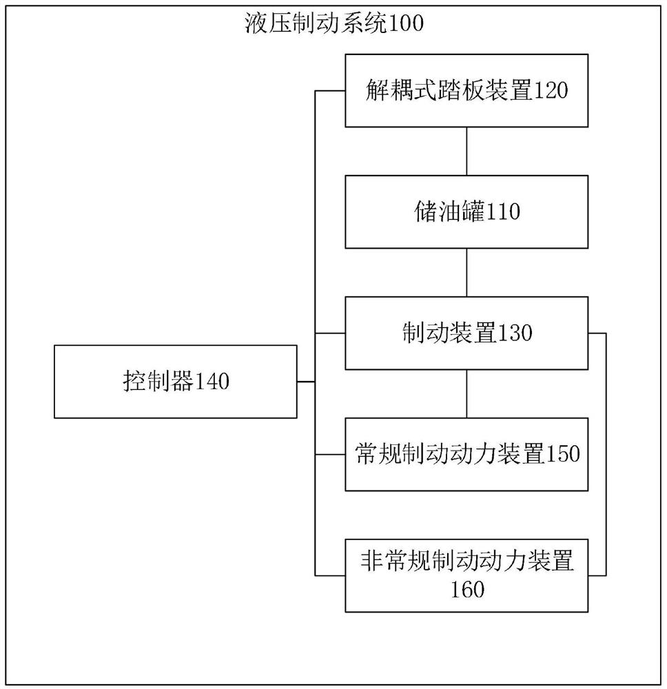
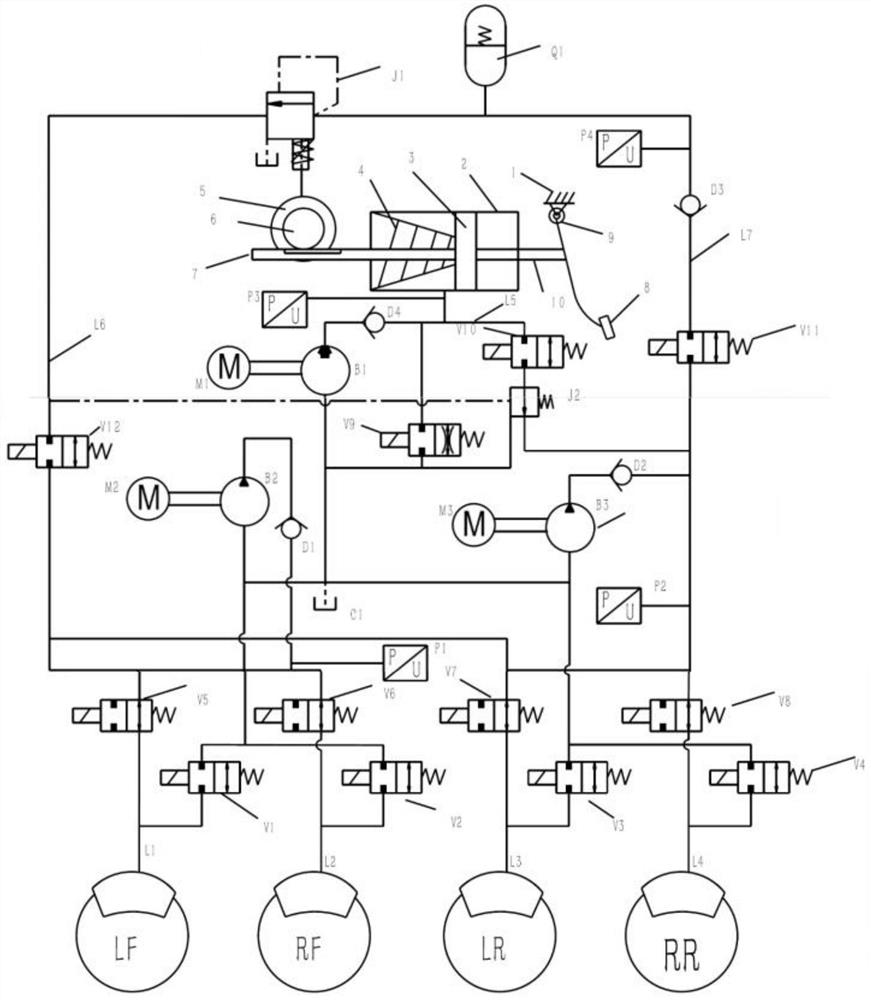
The invention discloses a hydraulic braking system and method, and relates to the field of automobile braking. The system comprises an oil storage tank, a decoupling type pedal device connected with the oil storage tank and used for collecting pedal braking information, a braking device connected with the oil storage tank and used for collecting oil pressure of a braking oil way and braking the vehicle, a controller connected with the decoupling type pedal device and the braking device and used for receiving pedal brake information and brake oil way oil pressure, obtaining the vehicle speed and generating a conventional brake instruction, and generating an unconventional braking instruction if the fault information is collected, a conventional braking power device connected with the braking device and the controller and used for receiving a conventional braking instruction to control the braking device to perform conventional braking, and a non-conventional braking device connected with the braking device and the controller and used for receiving a non-conventional braking instruction to control the braking device to perform non-conventional braking. Under the conditions that an electronic braking system fails and pedal assistance is lost, a driver is assisted in emergency braking through an unconventional braking device, and sudden increase of braking force is avoided.

Description

technical field [0001] The invention relates to the field of automobile braking, in particular to a hydraulic braking system and method. Background technique [0002] For the hydraulic braking system that adopts the complete decoupling of the brake pedal, there is generally a separate brake hydraulic cylinder as a backup for failure. In the event of an electronic braking system failure, pedal assist is lost and greater brake pedal effort is required to achieve the desired braking force. In an emergency situation, the sudden increase in brake pedal force is not conducive to vehicle control, and also limits the upper limit of the braking force that the driver can achieve. Contents of the invention [0003] The purpose of the present invention is to overcome the shortcomings of the above-mentioned background technology and provide a hydraulic braking system and method. When the electronic braking system fails and the pedal assist is lost, the driver is assisted in emergency ...

Claims


Application Information

Patent Timeline
Patent Type & Authority Applications(China)
IPC IPC(8): B60T13/66B60T13/68B60T13/74B60T13/14B60T17/22
CPCB60T13/14B60T13/662B60T13/686B60T13/745B60T17/22B60T2270/40
Inventor 李小刚王玉坤丁昶权
Owner DONGFENG MOTOR CORP HUBEI
Learn More