Mask production thread swinging and side clamping device
A production line and cycloid technology, used in household components, household appliances, other household appliances, etc., can solve problems such as reducing production capacity and affecting production efficiency, and achieve the effect of simplifying production process, improving efficiency, and small volume
- Summary
- Abstract
- Description
- Claims
- Application Information
AI Technical Summary
Problems solved by technology
Method used
Image
Examples
Embodiment 1
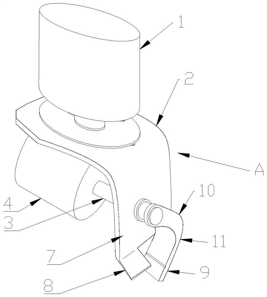
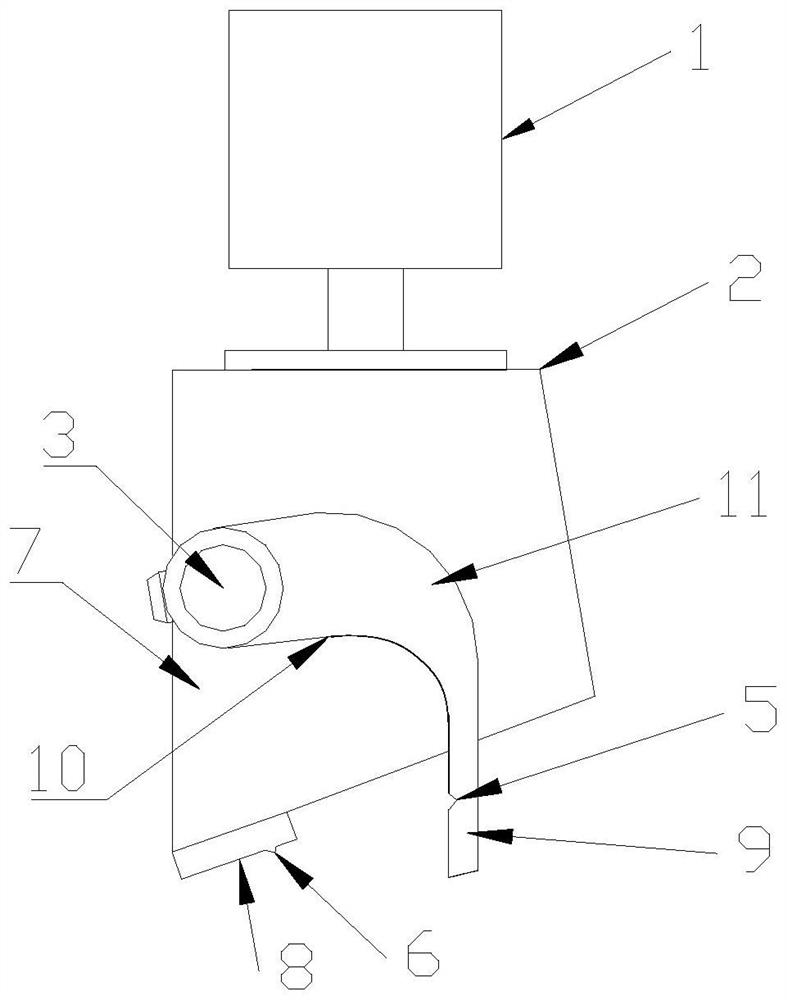
[0038] like figure 1 , 2 , the driving rod 3 is perpendicular to the movable clamp 10, and the driving rod 3 makes a reciprocating rotation at a set angle to complete the action of clamping and releasing the reset. In the releasing reset position, the lower end of the movable clamp end 9 is not lower than the lower end of the fixed clamp end 8 , and the movable clip end 9 has reached the reset position before crossing the ear wire, so that the movable clip end 9 will not conflict with the stretched ear wire to be intercepted during the cycloidal process of the side clamp device; The bottom of the remaining clamp end 8 is assembled at the lower end. The driver 4 can be directly formed by a stepping motor or a servo motor, or can be formed by a link mechanism driven by a DC motor to reciprocate.
[0039] from figure 1 , 2 It can be seen from the first embodiment that the movable clip 10 is not connected to the fixed base 2, but only connected to the output shaft of the drive...
Embodiment 2
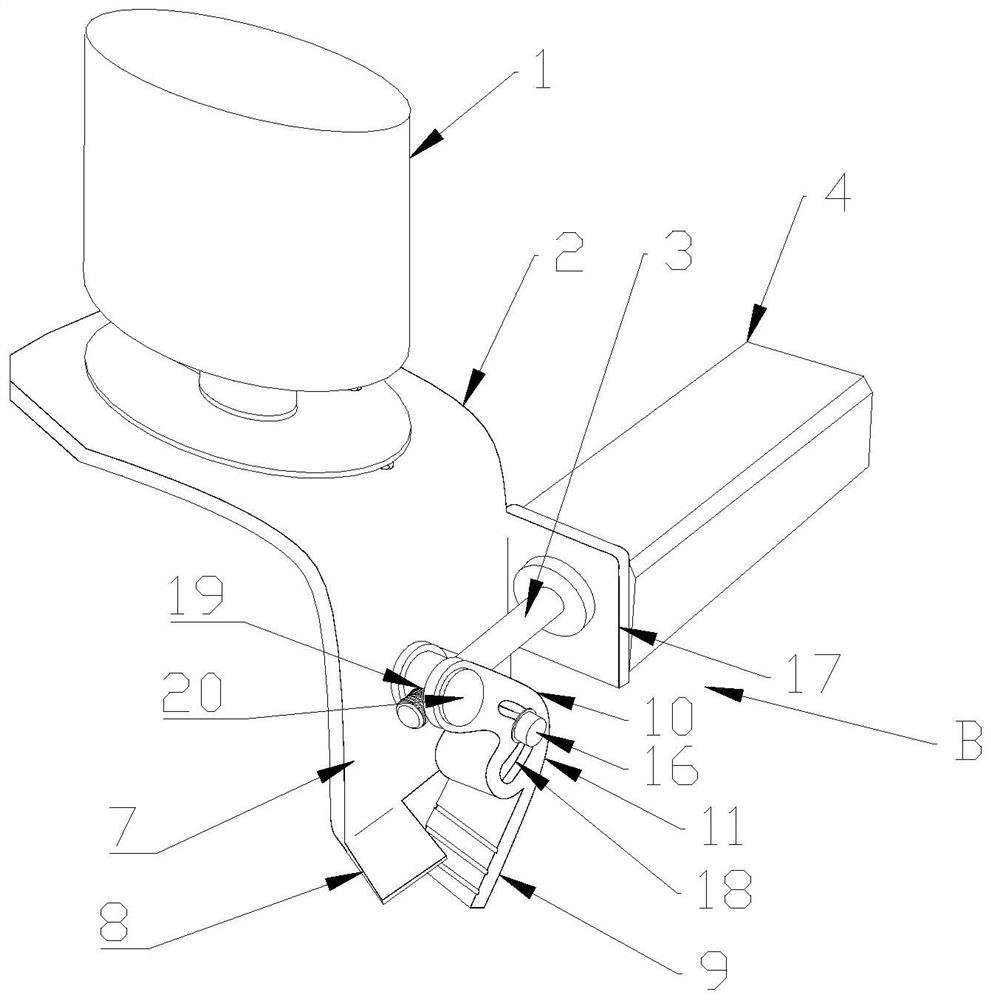
[0044] like image 3 , 4 , the swing arm 11 of the movable clamp 10 is provided with a swing pin 20 and a guide groove 18, the swing pin 20 is perpendicular to the movement plane of the movable clamp and is pivotally connected with the movable clamp 10 body, and the movement of the driving rod 3 and the movable clamp The planes are parallel, and the driver 4 is arranged on one side of the swing direction of the swing arm 11 . In fact, the fixed base 2 is integrally provided with a moving tool plate 17 on the side, the driver 4 is fixed to the moving tool plate 17, and the driving rod 3 performs telescopic movement or lateral swing. The driving rod 3 can be a cylinder or an electromagnet, or the motor can The driving rod 3 is driven to swing back and forth by the link mechanism. The outer end of the driver 4 is connected with the swing pin 20, and one end of the push-pull swing arm 11 moves back and forth when the drive rod 3 moves laterally.
[0045] The guide groove 18 is ...
PUM
 Abstract
Description
Claims
Application Information
 - Generate Ideas
- Intellectual Property
- Life Sciences
- Materials
- Tech Scout
- Unparalleled Data Quality
- Higher Quality Content
- 60% Fewer Hallucinations
Browse by: Latest US Patents, China's latest patents, Technical Efficacy Thesaurus, Application Domain, Technology Topic, Popular Technical Reports.
© 2025 PatSnap. All rights reserved.Legal|Privacy policy|Modern Slavery Act Transparency Statement|Sitemap|About US| Contact US: help@patsnap.com


