
Method for turning thin-wall steel jacket

A turning and steel sleeve technology, applied in the field of mechanical processing, can solve the problems of mass production waste, increasing the number of tool passes, wasting raw materials, etc., and achieve the effects of reducing cutting deformation, high processing accuracy, and sharp blades

Inactive Publication Date: 2021-02-26
CHANGZHOU INST OF MECHATRONIC TECH
View PDF0 Cites 3 Cited by
  • Summary
  • Abstract
  • Description
  • Claims
  • Application Information

AI Technical Summary

Problems solved by technology

[0010] However, increasing the margin of the inner hole of the thin-walled steel sleeve to solve the turning problem of the reference outer circle not only wastes raw materials, but also takes labor and time. The waste of mass production is astonishing. Turning the inner hole requires a lot of cutting times
Turning thin-walled steel sleeves on the faceplate can only solve the turning problem of large-diameter thin-walled sleeves, but cannot solve the turning problem of medium and small-diameter thin-walled steel sleeves.
When the inner hole and outer circle allowance of the thin-walled steel sleeve are normal, the three-jaw chuck cannot be used for clamping, and the turning problem of the reference outer circle cannot be solved.
Since there is no precise reference of the outer circle, the outer circle cannot be clamped with an open set, and the inner hole of the thin-walled steel sleeve cannot be turned; the outer circle cannot be clamped with a large arc-shaped soft claw, and the inner hole of the thin-walled steel sleeve cannot be turned; it cannot be clamped with a special fixture. Turning the inner hole of the thin-walled steel sleeve; even if it is turned, the coaxiality requirements of the inner and outer circles cannot be guaranteed at all

Method used


Image

  • Method for turning thin-wall steel jacket
  • Method for turning thin-wall steel jacket
  • Method for turning thin-wall steel jacket

Examples


Embodiment Construction

[0042] The technical solutions in the embodiments of the present invention will be clearly and completely described below in conjunction with the drawings in the embodiments of the present invention.

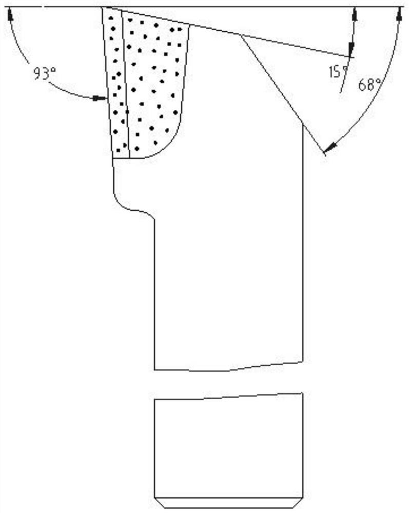
[0043] see Figure 1-8 Describe this embodiment, a kind of method of turning thin-walled steel sleeve:

[0044] 1. Process the thin-walled steel sleeve blank workpiece, which is the blank with normal allowance.

[0045]Heating the mixture of 96% carboxamide and 4% fire nitrate to above 140°C to make a self-coagulating agent, the self-coagulating agent has a large viscosity, strong adhesion, and a high coagulation speed, and the first A batch of self-coagulant 2 is filled into the inner hole of the workpiece 1, and the filling height is A. After the first batch of self-coagulant 2 is solidified, the height A is the length plus the length required for the three-jaw chuck of the lathe to clamp the workpiece 1 when the workpiece 1 is processed. 15mm;

[0046] After the first batc...


PUM

PropertyMeasurementUnit
angleaaaaaaaaaa
angleaaaaaaaaaa

Abstract

The invention provides a method for turning a thin-wall steel jacket, and belongs to the technical field of machining. The problems that existing thin-wall steel jacket workpieces are difficult to produce in batches, and progress cannot be guaranteed are solved. The method comprises the following steps that a mixture of 96% carbamide and 4% potassium nitrate is heated to 140 DEG C or above to prepare a self-coagulator, an inner hole of a workpiece is filled with the first batch of self-coagulator at a filling height of A, the inner hole of the workpiece is filled with a second batch of self-coagulator at a filling height of A after the first batch of self-coagulator is solidified, an upper end opening of the workpiece is covered with a rubber pad, the workpiece is turned by 180 degrees, the second batch of non-solidified self-coagulator is enabled to flow downwards, turning on an outer circle and the end face of the workpiece is performed after the second batch of self-coagulator are solidified, the workpiece is clamped by using a special clamp, and rough turning and finish turning on the inner hole of the workpiece are sequentially performed after clamping. The method is mainly used for batch machining on the thin-wall steel jacket.

Description

technical field [0001] The invention belongs to the technical field of mechanical processing, in particular to a method for turning thin-walled steel sleeves. Background technique [0002] Thin-walled steel sleeve refers to a thin-walled sleeve with only three dimensions: outer circle size, inner hole size, and length size, and the material is medium carbon steel. The wall thickness of thin-walled steel sleeve parts is very thin, and the radial rigidity is very weak. In the process of processing, it is affected by factors such as cutting force, cutting heat and clamping force, and is easily deformed. It is difficult to guarantee the roundness requirements and outer cylindricity requirements; it is difficult to guarantee the inner circle size requirements, inner roundness requirements, and inner cylindricity requirements of thin-walled sleeves; it is difficult to guarantee the coaxiality requirements of the inner and outer circles of thin-walled sleeves ensure. [0003] Ord...

Claims


Application Information

Patent Timeline
Patent Type & Authority Applications(China)
IPC IPC(8): B23B1/00B23Q3/00
CPCB23B1/00B23Q3/00B23Q2703/10
Inventor 徐嘉乐汤龙昊邹华杰周岳俞浩荣姚素芹袁志刚吴新平
Owner CHANGZHOU INST OF MECHATRONIC TECH
Learn More