
Positioning method, device and equipment for to-be-bent part of bending machine and storage medium

A positioning method and a technology of bending parts, which are applied in the field of workpiece positioning, can solve the problems of damaged and deformed stopper surfaces, waste products, easily damaged stopper surfaces, etc.

Active Publication Date: 2021-02-26
BEIJING A&E TECH
View PDF6 Cites 2 Cited by
  • Summary
  • Abstract
  • Description
  • Claims
  • Application Information

AI Technical Summary

Problems solved by technology

[0005]However, in the actual production process, due to the deviation of the stacking position of the parts to be bent on the material pile or the side edges of the parts to be bent to align the stoppers Factors such as unevenness will cause the robot to continue to move after the part to be bent is in partial contact with the stopper, so that the part to be bent is tightly pressed against the stopper, thereby causing a huge gap between the part to be bent and the stopper. In this case, not only the stress inside the part to be bent during bending will cause unnecessary deformation of the part to be bent, resulting in waste products, but also easily damage the surface of the stopper, causing the surface of the stopper to be damaged Deformation affects the positioning accuracy of subsequent parts to be bent
[0006] That is to say, when there is an interactive extrusion force between the piece to be bent and the stopper, it will not only affect the positioning accuracy of the piece to be bent, but also Directly affect the bending effect of the parts to be bent

Method used


Image

  • Positioning method, device and equipment for to-be-bent part of bending machine and storage medium
  • Positioning method, device and equipment for to-be-bent part of bending machine and storage medium
  • Positioning method, device and equipment for to-be-bent part of bending machine and storage medium

Examples


Embodiment Construction

[0050] The following will clearly and completely describe the technical solutions in the embodiments of the present invention with reference to the accompanying drawings in the embodiments of the present invention. Obviously, the described embodiments are only some, not all, embodiments of the present invention. Based on the embodiments of the present invention, all other embodiments obtained by persons of ordinary skill in the art without making creative efforts belong to the protection scope of the present invention.

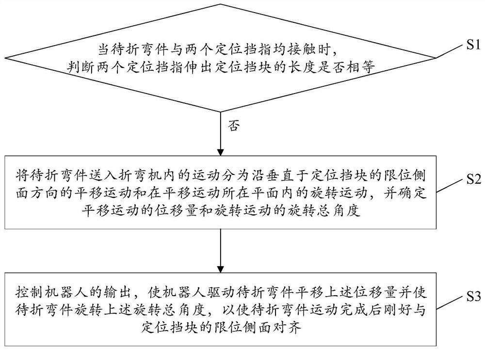
[0051] The core of the present invention is to provide a method for positioning the bending parts of the bending machine, which avoids the extrusion force between the bending parts and the positioning block during the positioning process of the bending parts. Another core of the present invention is to provide a positioning device, equipment and storage medium for parts to be bent of a bending machine, which have the above-mentioned advantageous effects.

[0052...


PUM


Abstract

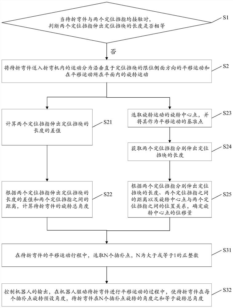
The invention discloses a positioning method, device and equipment for a to-be-bent part of a bending machine and a storage medium. The positioning method, device and equipment are applied to processcontrol over feeding of the to-be-bent part into the bending machine by a robot. The bending machine comprises a positioning stop block, wherein two telescopic positioning stop fingers are arranged onthe side, used for limiting the to-be-bent part, of the positioning stop block. The positioning method comprises the steps that when the to-be-bent part makes contact with the two positioning stop fingers, whether the lengths, stretching out of the positioning stop block, of the two positioning stop fingers are equal or not is judged; if not, the motion of feeding the to-be-bent part into the bending machine is divided into translation motion in the direction perpendicular to the limiting side face of the positioning stop block and rotation motion in the plane where the translation motion islocated, and the displacement of the translation motion and the total rotation angle of the rotation motion are determined; and the output of the robot is controlled, so that the robot drives the to-be-part part to horizontally move by the displacement and rotate by the total rotation angle, the to-be-bent part is just aligned with the limiting side face after moving is completed, and extrusion force generated between the to-be-bent part and the stop block is avoided.

Description

technical field [0001] The present invention relates to the technical field of workpiece positioning, and more specifically, relates to a positioning method, device, equipment and storage medium for a bending machine to be bent. Background technique [0002] In the field of mechanical processing technology, bending processing technology is usually involved, for example, bending processing of sheet metal parts. [0003] In actual production, robots are usually used to send the unformed parts to be bent into the bending machine to realize the feeding and positioning of the parts to be bent. There is a fixed stop in the bending machine to limit the position of the piece to be bent. When the robot puts the piece to be bent in place, one side of the piece to be bent will be in contact with one side of the stopper ; At this time, the bending knife of the bending machine moves downward, or the bending knife groove and the piece to be bent move upward at the same time, so that the ...

Claims


Application Information

Patent Timeline
IPC IPC(8): B21D11/22B21D11/00
CPCB21D11/22B21D11/00
Inventor 张志明
Owner BEIJING A&E TECH
Learn More