
Deuterated benzene catalytic reaction kettle with continuous catalytic function and working method thereof

A catalytic reaction, deuterated benzene technology, applied in the direction of chemical instruments and methods, chemical/physical processes, etc., can solve problems such as the inability to meet the needs of responsible processes

Inactive Publication Date: 2021-02-26
徐州亚兴医疗科技有限公司
View PDF4 Cites 0 Cited by
  • Summary
  • Abstract
  • Description
  • Claims
  • Application Information

AI Technical Summary

Problems solved by technology

[0002] In the production of deuterated benzene, the reagents need to be catalyzed, and the performance of continuous catalysis has a direct impact on the quality of the final produced reagents. Traditional reactors usually carry out mixing or conventional catalysis in the reactor, which cannot achieve the current responsible process. needs

Method used


Image

  • Deuterated benzene catalytic reaction kettle with continuous catalytic function and working method thereof
  • Deuterated benzene catalytic reaction kettle with continuous catalytic function and working method thereof

Examples


Embodiment 1

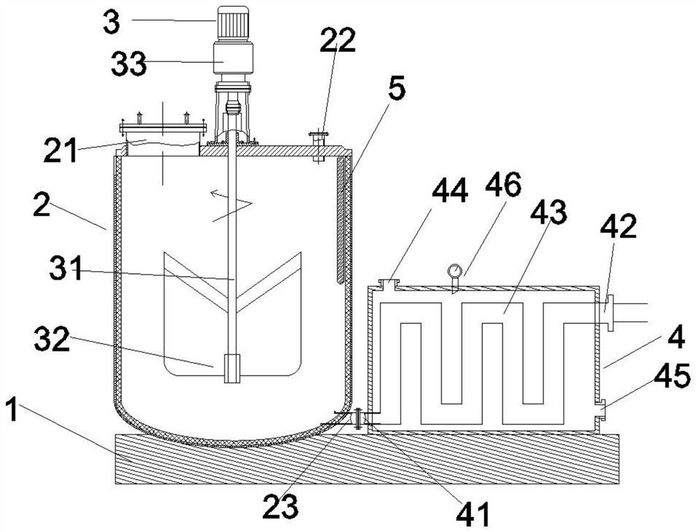
[0026] like figure 1 The shown deuterated benzene catalytic reactor with continuous catalytic function includes a base 1 , a mixing tank 2 , a discharge port 23 , a stirring motor 3 , a stirring shaft 31 , a stirring part 32 , a heat exchange box 4 and a liquid inlet 41 . Wherein, the mixing kettle 2 is arranged on one end of the base 1 , and the heat exchange box 4 is arranged on the base 1 and is located at one end close to the mixing kettle 2 . The stirring motor 3 is arranged on the mixing kettle 2 and is located in the middle of the top of the mixing kettle 2 . The stirring shaft 31 is arranged in the mixing kettle 2 , and one end is connected with the stirring motor 3 . The stirring part 32 is disposed on the end of the stirring shaft 31 away from the stirring motor 3 . The stirring part 32 is a plate-shaped stirring piece. The discharge port 23 is located at the bottom of the mixing tank 2 and is located at one end close to the heat exchange box 4 . The liquid inlet...

Embodiment 2

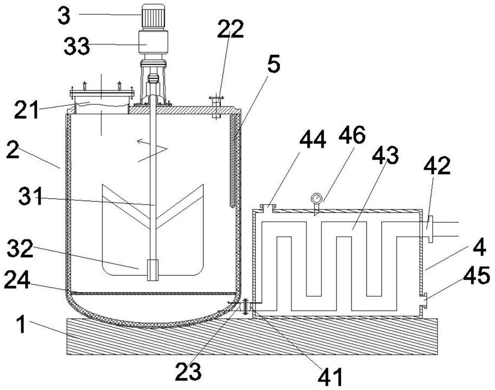
[0035] like figure 2The shown deuterated benzene catalytic reactor with continuous catalytic function includes a base 1 , a mixing tank 2 , a discharge port 23 , a stirring motor 3 , a stirring shaft 31 , a stirring part 32 , a heat exchange box 4 and a liquid inlet 41 . Wherein, the mixing kettle 2 is arranged on one end of the base 1 , and the heat exchange box 4 is arranged on the base 1 and is located at one end close to the mixing kettle 2 . The stirring motor 3 is arranged on the mixing kettle 2 and is located in the middle of the top of the mixing kettle 2 . The stirring shaft 31 is arranged in the mixing kettle 2 , and one end is connected with the stirring motor 3 . The stirring part 32 is disposed on the end of the stirring shaft 31 away from the stirring motor 3 . The stirring part 32 is a plate-shaped stirring piece. The discharge port 23 is located at the bottom of the mixing tank 2 and is located at one end close to the heat exchange box 4 . The liquid inlet...


PUM


Abstract

The invention discloses a deuterated benzene catalytic reaction kettle with a continuous catalytic function. The deuterated benzene catalytic reaction kettle mainly comprises a base, a mixing kettle,a discharge port, a stirring motor, a stirring shaft, a stirring part, a heat exchange box and a liquid inlet. The mixing kettle is arranged at one end of the base, and the heat exchange box is arranged on the base and located at the end close to the mixing kettle. The stirring motor is arranged on the mixing kettle and located in the middle of the top end of the mixing kettle. The stirring shaftis arranged in the mixing kettle, and one end is connected with the stirring motor. The stirring part is arranged at one end of the stirring shaft away from the stirring motor. And the stirring part is a plate-shaped stirring blade. The discharge port is formed in the bottom of the mixing kettle and is positioned at one end close to the heat exchange box. The liquid inlet is formed in the heat exchange box and is positioned at one end, close to the mixing kettle, of the lower part of the heat exchange box. And the discharge port is in flange connection with the liquid inlet.

Description

technical field [0001] The invention belongs to the field of production and processing of medical medicaments and medical equipment, in particular to a deuterated benzene catalytic reactor with continuous catalytic function and a working method thereof. Background technique [0002] In the production of deuterated benzene, the reagents need to be catalyzed, and the performance of continuous catalysis has a direct impact on the quality of the final produced reagents. Traditional reactors usually carry out mixing or conventional catalysis in the reactor, which cannot achieve the current responsible process. needs. Contents of the invention [0003] The object of the invention is to provide a deuterated benzene catalytic reactor with continuous catalytic function and its working method, which not only has the functions of mixing and conventional catalysis, but also can perform heat exchange catalysis. [0004] Technical solution: A deuterated benzene catalytic reactor with c...

Claims


Application Information

Patent Timeline
IPC IPC(8): B01J8/10
CPCB01J8/087B01J8/10B01J2208/00132B01J2208/00176
Inventor 张文池
Owner 徐州亚兴医疗科技有限公司
Learn More